Abrasive waterjet cutting depends on a continuous energy-transfer process. Electrical or hydraulic input is converted into pressurized water, the pressure is converted into jet velocity through a small orifice, and the high-speed water accelerates abrasive particles inside the mixing tube. The resulting abrasive jet removes material along the programmed cutting path.
Cutting performance is therefore not determined by pressure alone. Energy can be lost through unstable water supply, pump inefficiency, leakage, worn seals, restricted high-pressure tubing, damaged orifices, poor abrasive delivery, incorrect alignment and unsuitable cutting parameters.
Understanding this energy path helps operators diagnose reduced cutting speed, incomplete penetration, wider kerf, excessive taper and inconsistent edge quality more systematically.
In abrasive waterjet cutting, energy is transferred through a connected chain: the motor powers the pump, the pump converts this input into high-pressure water, the orifice converts pressure into jet velocity, and the high-speed water accelerates abrasive particles inside the mixing tube. The abrasive particles then transfer kinetic energy to the workpiece and remove material along the cutting path. Usable cutting energy decreases when pressure is unstable, high-pressure components leak, the orifice is damaged, abrasive flow is inconsistent, the mixing tube is worn or cutting speed is unsuitable.
The complete process can be divided into six stages:
Electrical energy powers the drive system
The pump converts drive energy into hydraulic or direct water pressure
High-pressure tubing transfers pressurized water to the cutting head
The orifice converts pressure energy into water-jet velocity
The water stream accelerates abrasive particles in the mixing chamber
The abrasive jet transfers energy to the workpiece and creates the kerf
Every stage influences the amount of usable energy that reaches the material. A pressure reading on the control panel only describes one part of this process. It does not confirm that the final abrasive stream is properly formed or efficiently removing material.
Three basic relationships help explain how pressure and flow become usable cutting energy.
Hydraulic power can be expressed as:
Pₕ = p × Q
Where:
Pₕ is hydraulic power in watts
p is water pressure in pascals
Q is volumetric water flow in cubic metres per second
This relationship shows why pressure alone does not describe the total available power. Two systems operating at the same pressure may provide different hydraulic power if their water-flow rates are different.
Ignoring system losses, ideal jet velocity can be approximated by:
v = √(2p ÷ ρ)
Where:
v is ideal water-jet velocity
p is water pressure
ρ is water density
Actual velocity is lower than the ideal value because the pump, tubing, valves, orifice and cutting head introduce efficiency losses.
The kinetic power carried by the accelerated abrasive can be described as:
Pₐ = ½ × ṁₐ × vₐ²
Where:
Pₐ is abrasive kinetic power
ṁₐ is abrasive mass flow rate
vₐ is abrasive-particle velocity
Because velocity is squared, particle acceleration has a strong influence on cutting power. However, adding more abrasive does not always increase useful power. Excessive abrasive loading can reduce particle acceleration, increase collisions inside the mixing process and raise operating cost.
These equations are simplified engineering relationships. Actual cutting performance also depends on pump efficiency, orifice condition, mixing efficiency, abrasive properties, material resistance, standoff distance and traverse speed.

The energy-transfer process begins with the motor and high-pressure pump. Depending on the system design, the pump may use a hydraulic intensifier or another suitable high-pressure generation method.
In an intensifier system, the motor drives a hydraulic pump. Hydraulic pressure acts on a larger piston area, while a smaller high-pressure plunger compresses the cutting water. This area difference allows the system to generate ultra-high water pressure.
The pump must provide both suitable pressure and stable delivery. A high displayed pressure with frequent fluctuations may still produce inconsistent cutting. Seal wear, valve leakage, poor water supply, contaminated filters or unstable hydraulic conditions can interrupt the pressure cycle and change the energy reaching the cutting head.
Operators should evaluate:
Working pressure during continuous cutting
Pressure stability rather than peak pressure alone
Pump cycling condition
Hydraulic-oil temperature
Seal and check-valve condition
Water-supply pressure and cleanliness
Unusual vibration, leakage or noise
Stable pump output provides the foundation for the remaining energy-transfer stages.
After the pump pressurizes the water, the energy must travel through high-pressure tubing, fittings, valves and connections before reaching the cutting head.
The high-pressure line should maintain a stable flow path without leakage, damaged connections or unnecessary restrictions. Even small leaks represent both an energy loss and a serious safety concern. Damaged fittings, incorrectly assembled tubing and worn high-pressure components can also create unstable operating conditions.
The routing of the high-pressure line should avoid excessive stress, unsupported vibration and unsuitable bending. Connections must be inspected according to the equipment manufacturer’s maintenance and safety requirements.
Before troubleshooting the cutting head, operators should confirm that:
The pump reaches stable working pressure
No visible leakage is present
Fittings and tubing are properly installed
Valves open and close correctly
The pressure remains stable when cutting begins
High-pressure components must never be inspected, tightened or disassembled while the system is pressurized.
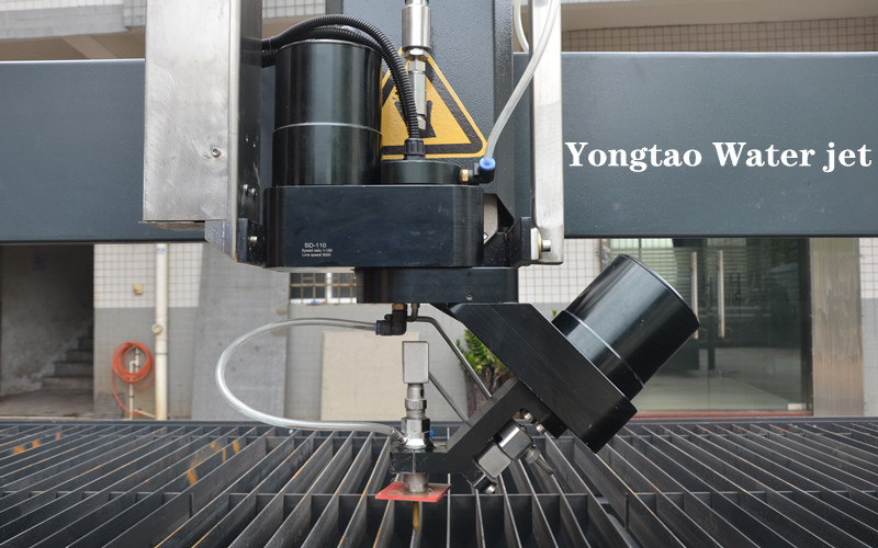
Inside the cutting head, pressurized water passes through a small orifice. The orifice converts pressure energy into a very high-speed water stream.
This conversion depends on the orifice diameter, condition and alignment. If the orifice is chipped, worn, contaminated or incorrectly seated, the emerging stream may become unstable or poorly focused. The system may still show normal pressure even though the useful jet quality has deteriorated.
Common signs of an orifice problem include:
Unstable or irregular jet shape
Faster mixing-tube wear
Wider or inconsistent kerf
Reduced cutting efficiency
Unexpected edge-quality changes
Difficulty maintaining accurate cutting
A larger orifice can increase water-flow demand, while a smaller orifice requires correct matching with the pump capacity and downstream components. Orifice selection should therefore be based on the complete system configuration rather than changed independently.
For hard materials such as metal, stone, ceramic and many composites, the water stream alone generally does not provide the required material-removal performance. Garnet or another suitable abrasive is introduced into the mixing chamber.
The high-speed water stream creates conditions that draw abrasive into the cutting head. The abrasive particles are then accelerated as they pass through the mixing or focusing tube.
Efficient energy transfer requires:
Stable abrasive delivery
Dry and free-flowing abrasive
Suitable abrasive particle size and quality
Correct orifice and mixing-tube relationship
Proper cutting-head alignment
A mixing tube in usable condition
Adding more abrasive does not automatically create more cutting power. If abrasive flow becomes excessive, the particles may not accelerate efficiently and operating costs can increase. If the flow is too low or intermittent, the jet may lose cutting capacity and produce uneven results.
The objective is a stable abrasive stream that matches the material, thickness, nozzle configuration and required cutting speed.
The mixing tube guides and focuses the abrasive stream before it reaches the workpiece. Because abrasive particles travel through it at high speed, the internal bore gradually wears.
As wear increases, the jet can become wider and less concentrated. This reduces the amount of energy delivered to a narrow cutting area and may increase kerf width, taper and surface roughness.
Typical signs of mixing-tube wear include:
Gradually increasing kerf width
Reduced dimensional consistency
More visible edge striations
Increased taper
Lower cutting capacity at unchanged settings
Faster deterioration of corner quality
Operators should not wait until the mixing tube completely fails. Kerf measurements, cutting hours and first-part inspection can be used to determine practical replacement intervals.
Orifice and mixing-tube alignment is equally important. Misalignment directs the high-speed water stream against the mixing-tube wall, causing rapid wear and inefficient abrasive acceleration.
When the abrasive stream reaches the workpiece, its remaining kinetic energy removes material through controlled erosion. The jet must continue through the full material thickness and exit from the bottom of the cut.
Energy is gradually lost as the stream travels deeper into the material. This is why thick or hard materials generally require slower movement than thin or softer materials. If the cutting head moves too quickly, the lower part of the jet falls behind the programmed path, producing greater jet lag, taper and surface striations.
The amount of usable cutting energy depends on:
Material type and hardness
Material thickness
Working pressure and stability
Water-flow condition
Abrasive type and flow rate
Orifice and mixing-tube condition
Cutting speed
Standoff distance
Pierce method
Machine motion stability
Cutting through the material does not automatically mean the selected parameters are suitable. The resulting dimensions, taper, edge texture and production cost must also be evaluated.

Increasing pressure can provide more jet energy under suitable system conditions, but pressure should not be treated as the only performance indicator.
If the abrasive supply is unstable, the mixing tube is worn or the orifice is damaged, increasing the pressure may not restore accurate cutting. Higher pressure can also increase stress on seals, tubing, fittings and other high-pressure components.
Before adjusting pressure, operators should determine where the energy loss occurs. The correct solution may involve repairing the pump, stabilizing the water supply, replacing a worn consumable, correcting abrasive flow or reducing cutting speed.
A complete-system diagnosis is more reliable than changing one parameter without checking the other stages.

When cutting performance decreases, inspect the energy path in sequence.
| Observed Symptom | Possible Energy-Loss Stage | First Inspection |
|---|---|---|
| Pressure fluctuates during cutting | Pump or incoming-water stage | Water supply, filters, seals, valves and pump cycling |
| Pressure is normal but cutting becomes weaker | Orifice, abrasive or mixing stage | Orifice condition, abrasive flow and cutting-head alignment |
| Kerf gradually becomes wider | Mixing-tube stage | Internal wear and nozzle combination |
| Edge quality changes suddenly | Abrasive delivery or pressure stage | Moist abrasive, blocked hose, feed valve and pressure stability |
| Lower edge shows heavy striations | Workpiece energy-transfer stage | Cutting speed, material thickness and abrasive delivery |
| Taper increases at unchanged settings | Nozzle, mixing tube or speed stage | Consumable wear, alignment and traverse speed |
| Abrasive consumption rises without better cutting | Abrasive acceleration stage | Abrasive flow rate and nozzle matching |
| Cutting stops before full penetration | Multiple possible stages | Pressure, abrasive delivery, nozzle condition and cutting speed |
Confirm adequate water supply, filter condition and water quality. Insufficient or contaminated water can affect pump operation and component life.
Check whether the working pressure remains stable during continuous cutting. Look for leakage, irregular cycling, abnormal temperature or unusual noise.
Examine tubing, valves, fittings and connections according to the required safety procedure. Do not approach or service pressurized components.
Check orifice condition, seating and jet stability. A damaged orifice can reduce cutting performance even when pressure appears normal.
Make sure the abrasive is dry and flowing continuously. Inspect the hopper, metering device, valve and supply hose for moisture, blockage or leakage.
Compare the current kerf width and edge condition with an approved sample or previous production record. A wider kerf may indicate mixing-tube wear or poor jet focus.
Confirm that the speed, pierce method and quality level match the material and thickness. Do not copy one parameter set across different materials without test cutting.
A short trial cut is one of the most practical ways to evaluate the complete energy-transfer chain. The test should use the actual material and thickness planned for production.
After cutting, inspect:
Complete penetration
Top and bottom dimensions
Kerf width
Edge taper
Surface striations
Corner accuracy
Piercing condition
Abrasive-flow stability
If the trial result is acceptable, record the material, thickness, pressure, abrasive setting, cutting speed, nozzle combination and measured result. These records provide a useful baseline for future troubleshooting.
Energy efficiency does not simply mean operating at the highest possible pressure. It means delivering sufficient, stable energy to the cutting zone while controlling abrasive use, consumable wear, production time and finished-part quality.
Factories can improve overall performance by:
Maintaining stable water quality and supply
Inspecting high-pressure components regularly
Replacing worn orifices and mixing tubes in time
Keeping abrasive dry and delivery stable
Matching speed to material thickness and quality requirements
Recording approved parameters for repeat jobs
Inspecting the first part before batch production
Evaluating cost per acceptable part rather than speed alone
A properly matched system converts more of its available energy into useful material removal and reduces losses caused by unstable cutting, rejected parts and unnecessary consumable replacement.
Higher pressure can increase water-jet velocity and power density when the pump, orifice, abrasive system and cutting head are properly matched. However, higher pressure cannot compensate for unstable abrasive flow, a worn mixing tube, damaged orifice, incorrect alignment or unsuitable cutting speed.
The pressure reading only describes one part of the energy-transfer chain. Cutting performance may decrease because the orifice is damaged, the abrasive supply is unstable, the mixing tube is worn, the cutting head is misaligned or the selected speed is too high for the material and thickness.
No. Too little abrasive may reduce cutting capacity, but excessive abrasive can reduce particle acceleration, increase collisions in the mixing process, accelerate component wear and raise operating cost. The objective is stable abrasive delivery matched to the nozzle, material and cutting requirements.
A worn mixing tube produces a wider and less concentrated abrasive stream. This distributes the available energy over a larger area and may cause wider kerf, increased taper, rougher edges and reduced dimensional consistency.
Inspect the system in sequence: incoming water, pump stability, high-pressure tubing, orifice condition, abrasive delivery, mixing-tube wear, kerf condition and cutting parameters. A trial cut using the actual material and thickness provides more reliable evidence than changing several settings at once.
Record the material, thickness, working pressure, abrasive setting, orifice and mixing-tube combination, cutting speed, pierce method, kerf measurement, taper, edge condition and inspection result. These records provide a baseline for later production and troubleshooting.
The energy relationships and process principles discussed in this article are consistent with established abrasive-waterjet research and engineering references, including:
Peter Miles, Abrasive Kinetic Cutting Power: A Function of Pressure, Abrasive Mass Flow and Pump Efficiency, WJTA Conference Proceedings.
M. Hashish, Abrasive Waterjet Machining, open-access technical review published in 2024.
Research on Energy Loss from an Abrasive Waterjet for Rock Cutting, WJTA Conference Proceedings.
Abrasive waterjet cutting is a connected energy-transfer process rather than a single pressure-generating action. The pump, high-pressure line, orifice, abrasive supply, mixing tube, cutting distance and programmed speed all determine how much usable energy reaches the workpiece.
When performance changes, operators should trace the process from the incoming water and pump to the final kerf. This approach helps identify the actual cause of energy loss and avoids unnecessary adjustments.
For information about available table sizes, axis options and complete equipment configurations, reviFor information about table sizes, axis configurations and complete equipment options, visit the Yongtao water jet cutting machine product page.
0086-18665475362
[email protected]
Road 3, Wuzhuang Xiaofengtian Ind. Zone, Luocun Town, Nanhai Dist., Foshan, Guangdong, China