

Custom hardware parts often include mounting plates, brackets, flanges, equipment panels, protective covers and non-standard components produced from stainless steel, carbon steel, aluminum or other alloys. These parts may contain irregular contours, internal holes, narrow sections and different dimensional requirements within the same drawing.
Abrasive waterjet cutting can process these components without introducing a conventional heat-affected zone. However, obtaining stable results requires more than importing a drawing and starting the cutting program. The material, part geometry, piercing method, cutting sequence, holding strategy and required edge quality should all be reviewed before production.
Abrasive waterjet process planning for custom hardware parts should begin with the finished drawing, material grade, plate thickness, critical tolerances and required edge quality. Internal holes and slots should normally be cut before the external profile, while pierce points should be placed in scrap areas or on controlled lead-in paths. Small parts may require temporary tabs to prevent movement or falling. Before batch production, the first completed part should be inspected for dimensions, hole position, kerf, taper, corner quality and surface striation.
| Planning Item | What to Confirm | Why It Matters |
|---|---|---|
| Drawing | Closed contours, duplicate lines, hole sizes and drawing revision | Prevents incomplete or repeated cutting paths |
| Material | Grade, actual thickness, flatness and visible face | Determines cutting parameters and loading direction |
| Kerf | Test-cut width and inside/outside compensation | Helps maintain finished-part dimensions |
| Piercing | Scrap location, lead-in path and sensitive features | Prevents pierce marks on finished edges |
| Cut sequence | Internal features before external profiles | Keeps the part stable during processing |
| Part holding | Tabs, support and fall prevention | Reduces part movement and collision risk |
| Cutting quality | Rough, standard or finished-edge requirement | Balances edge quality, time and cost |
| First-part inspection | Dimensions, holes, taper, corners and striations | Confirms settings before batch production |
| Production record | Drawing revision, nozzle, abrasive and speed | Improves repeatability for future orders |
Process planning should begin with the finished-part drawing. The operator should confirm the material grade, plate thickness, overall dimensions, hole sizes, internal contours, required tolerances and any surfaces that will be welded, bent or machined after cutting.
Small holes, narrow slots and sharp internal corners require particular attention. If a feature is too small in relation to the kerf width and material thickness, it may not be reproduced exactly as shown in the drawing. The drawing may need to be adjusted, or the feature may need to be completed by drilling or machining after profile cutting.
The following information should be confirmed before programming:
Material type and grade
Plate length, width and thickness
Finished-part dimensions
Critical holes and reference edges
Required dimensional tolerances
Required edge-quality level
Quantity of each component
Subsequent bending, welding or machining operations
This review helps the workshop distinguish critical dimensions from non-critical separation cuts and select an appropriate processing strategy.
Metal plates should be checked for flatness, surface contamination, protective film condition and existing deformation before loading. Dirt, loose scale or foreign material under the plate can affect support stability and cause the workpiece to move during cutting.
The plate should be supported evenly on the cutting table. Large unsupported areas may vibrate, while small parts can fall or tilt after their contours are completed. When the material has a directional surface finish, protective coating or visible face, its loading direction should also be recorded.
If a batch contains plates from different suppliers or production lots, the operator should verify their actual thickness instead of relying only on the nominal specification.
CAD geometry should be inspected for open contours, overlapping lines, duplicated entities and very short segments. These drawing problems can cause unnecessary machine movement, repeated cutting or incomplete profiles.
Kerf compensation should be applied according to whether the programmed contour is an internal or external feature. External profiles and internal holes require different compensation directions. The correct offset depends on the cutting-head setup, abrasive condition, material, thickness and selected cutting quality.
For first-time parts, a short test cut can be used to confirm:
Actual kerf width
Hole-size result
Outside dimension
Corner condition
Edge taper
Surface striation
Required cutting speed
The verified parameters should be saved with the part number, material and thickness for future repeat orders.
Not every feature shown in a CAD drawing should be processed with the same cutting strategy. Small holes, narrow slots, sharp internal corners, thin webs and closely nested contours may require additional review because the available kerf, material thickness and jet behavior can limit the finished geometry.
The following features should be checked before programming:
Holes that are small relative to the plate thickness
Narrow slots with limited space for kerf compensation
Sharp internal corners that require a practical corner radius
Thin sections that may vibrate or deform after release
Closely spaced contours that leave weak material between parts
Reference edges that will be used for later bending or machining
Visible edges that require reduced piercing marks or striations
If a critical feature cannot be produced reliably by profile cutting alone, it should be identified before production and assigned to a suitable secondary operation such as drilling, reaming or machining. This decision should be based on the drawing, test-cut result and required tolerance rather than a general minimum-feature claim.
Piercing should normally begin in scrap areas or on lead-in paths rather than directly on a critical finished edge. This reduces the chance that the initial piercing mark will affect the final contour.
For internal openings, the pierce point should be positioned far enough from the finished boundary to allow a controlled lead-in. The available distance depends on the opening size, material thickness and cutting-head movement.
Sensitive locations to avoid include:
Finished corners
Narrow webs between two contours
Small functional holes
Visible decorative edges
Areas close to a bend line
Sections requiring later precision machining
When the material or thickness makes direct piercing difficult, the workshop should evaluate reduced-pressure piercing, low-pressure piercing, pre-drilled start holes or another suitable piercing procedure.
The cutting sequence affects part stability, dimensional consistency and production efficiency. Internal holes and slots are generally completed before the external contour so that the workpiece remains supported while its internal features are processed.
A practical sequence for many custom hardware parts is:
Cut small internal holes
Cut larger internal openings
Complete slots and internal contours
Cut shared or adjacent boundaries where appropriate
Finish the external profile
Leave unstable or easily displaced parts until later
Cutting all outer contours first can release components too early. Once a part moves, tilts or falls between the support slats, its remaining features may no longer align with the original coordinate position.
For sheets containing many different components, the sequence should also minimize unnecessary traverse movement while maintaining adequate plate stability.
Small hardware components can shift or fall into the cutting tank when their external contours are completed. Temporary holding tabs can keep these parts connected to the surrounding material until the cutting program is finished.
Tab size and position should be selected according to the part dimensions, material thickness and later removal method. Tabs should not be placed on a critical reference surface or in a location that is difficult to grind.
Too few tabs may allow the component to move. Excessively large tabs increase manual removal and finishing work. The objective is to use only enough holding force to keep the part stable during cutting.
Nesting should balance material utilization with reliable processing. Placing parts extremely close together may save plate area, but it can also leave narrow strips that deform, vibrate or break during cutting.
The nesting plan should consider:
Minimum spacing between adjacent contours
Distance from the plate edge
Pierce-point clearance
Cutting-head access
Part-removal space
Material grain or surface direction
Heat-free processing requirements
Reusable remnant dimensions
Common-line cutting may reduce cutting distance for suitable components, but it should only be used when both parts can share the same cut without affecting dimensional tolerances or edge requirements.
Not every edge requires the same cutting speed or surface finish. A concealed bracket with generous tolerance may use a faster production cut, while a visible panel, alignment feature or component with limited secondary finishing may require a slower quality cut.
Cutting speed influences edge taper, surface striation, dimensional consistency and operating cost. Slowing the entire program to the highest quality level may waste production time. A better approach is to assign suitable quality levels to different contours according to their function.
Critical holes and mating edges can receive higher-quality settings, while non-critical separation edges can use more economical parameters.
The first part should be inspected before the full batch continues. This is particularly important for new drawings, new materials or revised parameter files.
Inspection should include:
Overall length and width
Hole diameters and center distances
Slot width and position
Internal and external contour dimensions
Top-to-bottom edge taper
Corner condition
Surface striation
Burr or attached tab condition
Flatness and visible deformation
Suitability for subsequent welding, bending or machining
Any adjustment should be made according to the inspection result rather than by changing several parameters at the same time. Controlled adjustments make it easier to identify the cause of dimensional or edge-quality differences.
| Inspection Result | Possible Cause | Recommended Review |
|---|---|---|
| Outside dimensions are incorrect | Kerf offset or drawing scale | Verify CAD scale and external compensation direction |
| Holes are too large or too small | Incorrect internal offset or worn nozzle | Check compensation and measure current kerf |
| Top and bottom dimensions differ | Edge taper or excessive cutting speed | Review speed, nozzle condition and taper requirement |
| Lower edge has heavy striations | Cutting speed too high or insufficient jet energy | Reduce speed and inspect pressure and abrasive delivery |
| Small parts move during cutting | Insufficient support or missing tabs | Adjust support, tab position and cutting sequence |
| Pierce mark affects the edge | Pierce point too close to the contour | Move the pierce into scrap and use a controlled lead-in |
| Quality changes during the batch | Consumable wear or unstable abrasive flow | Inspect the nozzle and abrasive supply system |
Once the first part is approved, the workshop should record the drawing revision, material grade, thickness, nozzle condition, abrasive setting, cutting speed, pierce method, quality level and inspection result.
A repeatable production record reduces setup time for later orders and helps different operators follow the same process. It also provides useful information when material thickness, abrasive quality or nozzle condition changes.
For batch production, nozzle wear and abrasive delivery should be checked at planned intervals because gradual changes can affect kerf width, taper and edge appearance.
Abrasive waterjet processing is particularly useful for custom hardware components when the project involves mixed metal materials, irregular contours, low- or medium-volume production, thick plate, reflective alloys or parts that should avoid conventional thermal influence.
Typical components include:
Equipment mounting plates
Machine brackets
Flanges and connecting plates
Stainless steel covers
Control-panel openings
Aluminum equipment panels
Decorative hardware parts
Prototype metal components
Custom holes and profiles
Parts prepared for later bending or welding
The final process should always be selected according to the drawing, material, thickness, required tolerance and production quantity. Waterjet processing is not automatically the fastest or lowest-cost method for every component, but it provides useful flexibility when cold cutting, complex geometry and material versatility are important.
Before evaluating a custom hardware project, the manufacturer should provide:
CAD or DXF drawing
Material name and grade
Plate thickness
Maximum plate dimensions
Required quantity
Critical tolerances
Required edge quality
Subsequent manufacturing operations
Visible-surface requirements
Expected delivery schedule
Internal holes, slots and enclosed contours should generally be completed before the external profile. This keeps the component connected to the surrounding plate while its critical internal features are cut. Small or unstable parts should be processed later in the sequence or retained with suitable tabs.
A test cut helps verify the actual kerf, dimensional offset, hole size, edge taper, corner condition and required cutting speed for the selected material and thickness. These results are more reliable than applying an unverified parameter set from another material or job.
The pierce point should normally be placed in scrap material or on a lead-in path away from a critical finished edge. Finished corners, narrow webs, small holes, visible surfaces and later machining references should be avoided whenever possible.
Holding tabs may be needed when small parts could move, tilt or fall into the cutting tank after their external profiles are completed. Tab size and location should maintain stability without creating unnecessary finishing work on critical edges.
The production record should include the drawing revision, material grade, actual thickness, nozzle condition, abrasive setting, cutting speed, pierce method, quality level, kerf measurement and first-part inspection result.
No. Feasibility depends on hole size, material thickness, kerf, taper, nozzle configuration and required tolerance. Critical holes may require drilling, reaming or machining after the waterjet profile is completed.
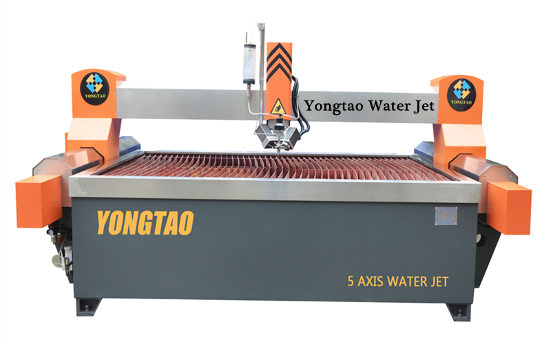
Yongtao can review material information, finished-part drawings and production requirements to help customers compare suitable table sizes, axis configurations and supporting equipment. For machine specifications and available configurations, visit the Yongtao water jet cutting machine product page.
 0086-18665475362
[email protected]
Road 3, Wuzhuang Xiaofengtian Ind. Zone, Luocun Town, Nanhai Dist., Foshan, Guangdong, China
 0086-18665475362
 [email protected]
 Road 3, Wuzhuang Xiaofengtian Ind. Zone, Luocun Town, Nanhai Dist., Foshan, Guangdong, China
 English
 Español