
EN
YJ-4020-3L 3 Axis Water Jet Glass Cutting Machine

YJ-4020-3L 3 Axis Water Jet Glass Cutting Machine

4000 × 2000 mm 3-Axis Gantry Waterjet Cutter for Large Glass Panels
YJ-4020-3L 3 Axis Water Jet Glass Cutting Machine
  • YJ-4020-3L 3 Axis Water Jet Glass Cutting Machine
  • YJ-4020-3L 3 Axis Water Jet Glass Cutting Machine
  • YJ-4020-3L 3 Axis Water Jet Glass Cutting Machine
  • YJ-4020-3L 3 Axis Water Jet Glass Cutting Machine
  • YJ-4020-3L 3 Axis Water Jet Glass Cutting Machine

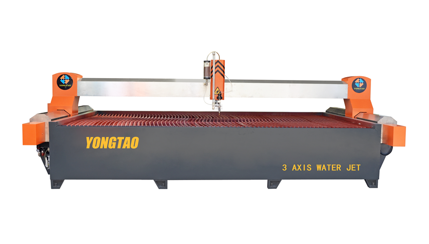
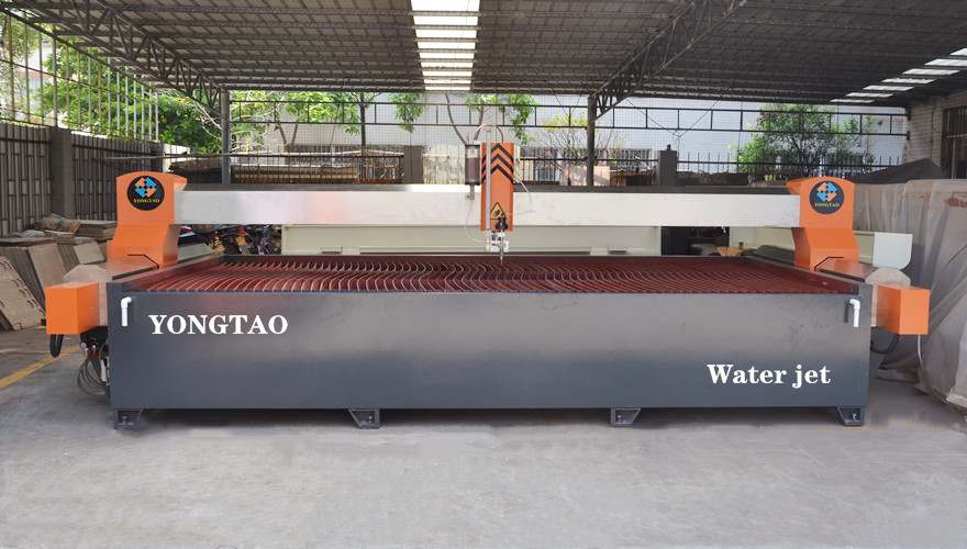
The YJ-4020-3L Water Jet Cutting Machine is a large-format, three-axis CNC system manufactured by Yongtao in Foshan, Guangdong, China. It provides a 4000 × 2000 mm cutting area for processing large glass panels and flat sheets without repositioning the workpiece.

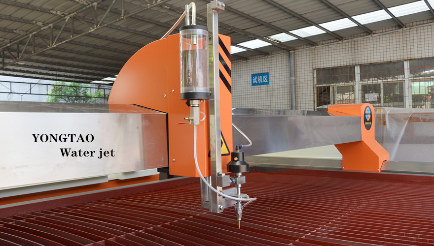
Equipped with X-, Y- and Z-axis motion, AC servo control and a vertically oriented cutting head, the machine performs straight 90-degree cutting, curves, internal openings and custom two-dimensional profiles. Its bridge structure, protected linear motion components and ultra-high-pressure system are designed for stable industrial production.

The YJ-4020-3L Glass Waterjet Cutter is primarily configured for flat glass processing. With appropriate cutting parameters, abrasive settings and consumables, it can also process stone, marble, granite, quartz, ceramics, stainless steel, steel plates, alloy steel and aluminum.

Quick Answer

The YJ-4020-3L is a 4020 Waterjet Cutting Machine with a maximum cutting range of 4000 × 2000 mm, a 130 mm Z-axis travel and stated cutting accuracy of ±0.1 mm. Its maximum system pressure is 420 MPa, while the normal operating-pressure range is 300–380 MPa.

This model is suitable for manufacturers that need a Large-Format Glass Waterjet Cutter for flat panels, holes, curves and irregular two-dimensional shapes. Because it is a three-axis model with a vertical cutting head, it is intended for straight 90-degree cutting rather than angled or bevel cutting.

Key Specifications at a Glance

ItemYJ-4020-3L specification
ModelYJ-4020-3L
Machine structureBridge-type gantry
Axis configurationX, Y and Z axes
Cutting range4000 × 2000 mm
Cutting table size4100 × 2100 mm
X-axis travel4000 mm
Y-axis travel2000 mm
Z-axis travel130 mm
Cutting accuracy±0.1 mm
Repeatability±0.05 mm
Maximum pressure420 MPa
Operating pressure300–380 MPa
Main motor power30 kW
Total installed power37 kW
Gem orifice diameter0.33 mm
Abrasive nozzle diameter1.0 mm
Maximum water flow11.1 L/min
Maximum abrasive consumption190 g/min
Traverse speed6000/15000 mm/min
CNC controllerAC servo system
Drawing preparationAutoCAD-compatible workflow
Power supply380 VAC, 50 Hz, three-phase

Specifications describe the standard configuration currently listed for this model. Final cutting thickness, speed and edge quality depend on the material, glass condition, pump configuration, abrasive specification, nozzle condition, cutting path and required finish. A sample cutting test is recommended before final production parameters are confirmed.

Why Choose the YJ-4020-3L?

Large 4000 × 2000 mm Cutting Area

The 4000 x 2000 Waterjet Cutter provides enough working space for large flat sheets and glass panels. Processing a large workpiece in one setup reduces repositioning, protects alignment and makes it easier to nest multiple parts within the available cutting area.

Compared with a smaller table, the 4m x 2m Waterjet Cutting Machine is better suited to factories that regularly receive large panels or need to arrange several components in one cutting program. The 4100 × 2100 mm waterjet cutting table supports a stated effective working range of 4000 × 2000 mm.

Practical Three-Axis Configuration

The YJ-4020-3L 3 Axis Water Jet Cutter controls movement along the X, Y and Z axes. The cutting head remains vertically oriented, allowing the machine to produce straight 90-degree cuts, curves, holes, slots and irregular flat profiles.

This configuration is appropriate when angled cutting is not required. It also avoids unnecessary multi-axis complexity for factories whose work consists mainly of two-dimensional flat-sheet processing.

The 4020 3 Axis Waterjet Cutting Machine is therefore a practical choice for buyers who prioritize a large working area, straightforward operation and stable CNC path control.

Stable Bridge-Type Gantry

The YJ-4020-3L Gantry Waterjet Cutter uses a crossbeam supported at both sides. This bridge-type arrangement distributes the moving structure across two supports and helps maintain consistent motion over the large cutting area.

High-precision ball screws and linear guides support controlled axis travel. AC servo drives respond to commands from the CNC controller, producing coordinated movement along the programmed cutting path. The rigid structure is intended to reduce unwanted movement during acceleration, positioning and continuous contour cutting.

Protected Linear Motion Components

Water, abrasive particles and cutting residue can shorten the service life of exposed motion components. The machine therefore uses a labyrinth-style waterproof and sand-resistant rail design with dual protective curtains.

Stainless-steel protective covers help shield the guides and transmission components from water, abrasive contamination, rust and corrosion. These protections also simplify routine cleaning around the cutting table.

Protective covers must still be inspected regularly. Accumulated abrasive, damaged curtains or contaminated lubrication should be corrected before they affect axis movement.

CNC Control and Cutting Workflow

The 4020 CNC Waterjet Machine combines an AC Servo CNC Controller with coordinated X-Y-Z movement. The operator prepares the required part geometry, checks the dimensions and cutting path, and transfers the processed program to the CNC control system.

The typical production sequence is:

  1. Prepare and verify the two-dimensional drawing.

  2. Confirm the workpiece dimensions and material condition.

  3. Set the cutting path, lead-in position and part spacing.

  4. Select pressure, cutting speed and abrasive settings.

  5. Position the sheet securely on the cutting table.

  6. Confirm that the nozzle path is clear.

  7. Perform a controlled trial or edge test when necessary.

  8. Start the CNC cutting program.

  9. Inspect the finished dimensions and edge condition.

The AutoCAD-Compatible Waterjet Machine workflow allows drawings created in CAD software to be prepared for CNC cutting. File conversion and toolpath generation should be completed with the software supplied or approved for the machine’s control system.

Complete Waterjet System Configuration

The standard production system consists of the main cutting units required for abrasive waterjet operation:

  • 4000 × 2000 mm CNC cutting table

  • Ultra-high-pressure intensifier system

  • CNC control cabinet

  • Automatic abrasive feeding system

  • Cutting head and abrasive delivery components

  • Recirculating cooling tower

  • High-pressure tubing and connections

  • Electrical and servo control system

The high-pressure system delivers a maximum rated pressure of 420 MPa. Normal operating pressure is listed at 300–380 MPa and should be selected according to the material, thickness, piercing method, cutting-speed requirement and desired edge quality.

The 420 MPa Waterjet Cutting System uses a 0.33 mm gem orifice and a 1.0 mm abrasive nozzle in the stated configuration. Maximum water flow is 11.1 L/min, while maximum abrasive consumption is listed at 190 g/min.

The automatic abrasive feeding system and sand valve are designed to maintain stable abrasive delivery. Clean, dry and correctly sized abrasive should be used to reduce flow interruption and premature wear.

Glass Processing Capability

Large Glass Panels and Flat Sheets

The Waterjet Cutter for Large Glass Panels provides a 4000 × 2000 mm processing range for straight edges, curves, internal openings and custom flat profiles. It is suitable for large sheets that fit within the machine’s effective cutting area and load-bearing conditions.

The 4020 Waterjet Machine for Flat Glass follows the programmed path without requiring a dedicated mold for every new profile. This is useful for customized components, sample production, different part sizes and small or medium production batches.

Controlled Piercing and Edge Quality

Glass is sensitive to concentrated impact during piercing. The entry position, initial pressure, nozzle height, abrasive flow and lead-in path must therefore be selected carefully.

Piercing should begin away from a critical finished edge whenever the drawing permits. A controlled starting method and appropriate pressure can help reduce the risk of cracking or chipping. Actual settings must be verified using the same type and thickness of glass intended for production.

The CNC Glass Waterjet Cutting Table can produce clean contours and internal openings, but the final edge quality depends on cutting speed, abrasive quality, nozzle condition and the required finish. Secondary edge treatment may still be required when the finished product has strict visual, handling or installation requirements.

Tempered glass should normally be cut before tempering. Cutting fully tempered glass can release its internal stress and cause the entire sheet to break.

Compatible Flat Materials

Although this model is positioned as a 4020 Glass Waterjet Cutting Machine, its abrasive cutting system can process several categories of flat material when the correct parameters are used.

Suitable material categories include:

  • Glass panels

  • Stone and marble

  • Granite and quartz

  • Ceramic materials

  • Stainless steel

  • Steel and alloy steel plates

  • Aluminum sheets

The listed maximum cutting thickness is up to 50 mm for glass, stone and ceramic materials and up to 40 mm for metals. These values should be treated as configuration limits rather than guaranteed production results for every material.

Before accepting a production order, the factory should verify the material grade, thickness, dimensions, required tolerance, acceptable edge quality and expected cutting speed through a sample test.

Accuracy and Production Verification

The machine’s stated cutting accuracy is ±0.1 mm, and its stated repeatability is ±0.05 mm. These figures describe the machine configuration under suitable operating and maintenance conditions.

Actual finished-part accuracy can also be influenced by:

  • Cutting-speed selection

  • Kerf compensation

  • Nozzle wear

  • Abrasive consistency

  • Material movement

  • Piercing method

  • Drawing accuracy

  • Workpiece flatness

  • Machine calibration

  • Required edge-quality level

For critical work, measure a representative test piece before batch production. The inspection should record the material, thickness, pressure, speed, abrasive setting, nozzle combination, measured dimensions and edge-quality acceptance criteria.

This type of verification provides more useful production evidence than relying on a single nominal accuracy figure.

Maintenance Features

Reliable cutting depends on the condition of both the motion system and the high-pressure components. Recommended routine checks include:

  • Remove accumulated abrasive and cutting residue.

  • Inspect protective curtains and stainless-steel covers.

  • Check ball screws, linear guides and lubrication points.

  • Confirm that the abrasive valve feeds consistently.

  • Examine the gem orifice and abrasive nozzle for wear.

  • Inspect high-pressure tubing, fittings and connections.

  • Monitor the intensifier and cooling system.

  • Verify axis positioning and repeatability.

  • Check water quality and inlet conditions.

  • Keep maintenance and replacement records.

The sand valve should be kept clean and dry to prevent unstable abrasive delivery. Worn nozzles should be replaced before the enlarged cutting stream affects kerf width, accuracy or edge quality.

Packaging Dimensions and Installation Planning

The main units are packed separately for transport:

ComponentApproximate packaging dimensions
Cutting table5.1 × 3.2 × 1.65 m
High-pressure booster system1.3 × 0.95 × 1.25 m
Abrasive feeder0.6 × 0.6 × 0.95 m
Control system0.65 × 0.65 × 1.67 m

Before ordering, the buyer should confirm workshop access, unloading capacity, foundation conditions, operating space, power supply, inlet water, drainage, cooling requirements, compressed air requirements and local electrical standards.

Adequate clearance should be reserved around the table, high-pressure system and control cabinet for operation, cleaning and maintenance.

Who Should Choose This Model?

The YJ-4020-3L is suitable for factories that:

  • Need a 4000 × 2000 mm processing range.

  • Mainly perform straight 90-degree cutting.

  • Process large flat sheets or glass panels.

  • Need CNC cutting of curves and internal openings.

  • Do not require angled or bevel cutting.

  • Want a complete abrasive waterjet configuration.

  • Can provide the required workshop utilities and maintenance support.

Factories that require frequent angled profiles or bevel cutting should evaluate a multi-axis configuration instead. Buyers should choose the axis configuration according to the actual finished-part geometry, not simply the number of available axes.

Technical Selection Summary

The YJ-4020-3L combines a large cutting area, three-axis CNC movement, a bridge-type structure, AC servo control and a maximum rated pressure of 420 MPa.

Its main selection advantages are:

  • 4000 × 2000 mm effective cutting range

  • 4100 × 2100 mm cutting table

  • Straight 90-degree cutting configuration

  • ±0.1 mm stated cutting accuracy

  • ±0.05 mm stated repeatability

  • 130 mm Z-axis travel

  • 300–380 MPa operating-pressure range

  • Complete cutting, pressure, abrasive and control systems

To receive an accurate YJ-4020-3L configuration and quotation, provide the material type, maximum sheet dimensions, thickness range, required cutting shapes, production volume, accuracy requirement, acceptable edge quality, factory voltage and destination country. Yongtao will use this information to confirm the cutting table, high-pressure system, CNC configuration, accessories, shipping requirements and technical support plan.

YJ-4020-3L Frequently Asked Questions

What is the working area of the YJ-4020-3L?

The machine has a maximum effective cutting range of 4000 × 2000 mm. Its listed cutting table size is 4100 × 2100 mm. This makes it suitable for large flat sheets and glass panels that fit within the stated working area.

Is the YJ-4020-3L a three-axis machine?

Yes. It uses coordinated X-, Y- and Z-axis movement. The cutting head remains vertically oriented for straight 90-degree cutting, curves, holes and irregular two-dimensional profiles. It is not intended for angled or bevel cutting.

What is the maximum pressure?

The maximum rated system pressure is 420 MPa. The listed normal operating range is 300–380 MPa. Actual pressure should be selected according to the material, thickness, piercing method, cutting speed and required edge quality.

What accuracy can the machine achieve?

The stated cutting accuracy is ±0.1 mm, and the stated repeatability is ±0.05 mm. Actual finished-part results depend on calibration, nozzle condition, cutting parameters, material stability, kerf compensation and inspection method.

Can the machine process large glass sheets?

Yes. The machine is designed as a Waterjet Machine for Large Glass Sheets with a 4000 × 2000 mm cutting area. The actual sheet must fit the working area and comply with the table’s loading and support requirements.

Can it cut holes and irregular profiles in glass?

Yes. The CNC system can follow programmed two-dimensional paths for holes, curves and irregular profiles. Glass piercing parameters must be controlled carefully to reduce cracking and edge chipping.

Can it cut tempered glass?

Glass should generally be cut before tempering. Fully tempered glass contains internal stress and may break completely if cutting is attempted after tempering. Confirm the glass condition before processing.

Does the machine support CAD drawings?

The system supports an AutoCAD-compatible workflow. Drawings can be prepared in CAD software and converted into a format accepted by the supplied CNC programming system. The drawing and cutting path should be checked before production begins.

Specification and Application Note

The technical data on this page describes the standard YJ-4020-3L configuration. Cutting thickness, speed, accuracy and edge quality vary with the material, pump configuration, abrasive, nozzle condition, cutting parameters and production environment.

Final performance should be confirmed through a representative material test and an approved technical configuration before shipment or batch production.


Recommend Products
Contact Us