Waterjet tile cutting for parquet and mosaic production is a controlled manufacturing process in which individually programmed ceramic, porcelain, stone or sintered-material pieces are cut and assembled into a finished decorative pattern. The result depends not only on the accuracy of the drawing, but also on kerf compensation, joint allowance, material direction, piercing strategy, cutting sequence and assembly control.
A successful floor medallion or tile inlay must satisfy two requirements at the same time: every individual piece must remain dimensionally acceptable, and all pieces must fit together as one complete pattern. For this reason, process planning should begin with the finished assembly rather than with the cutting path alone.

A complete tile parquet workflow normally includes reviewing the finished design, confirming the materials, separating and numbering each component, nesting the parts, applying kerf and joint compensation, selecting piercing positions, completing a test cut, cutting and sorting the pieces, performing a dry assembly, applying backing or adhesive, pressing the pattern and completing final inspection.
The most important control point is the test assembly. A piece can match its individual drawing but still create an unacceptable joint when combined with adjacent parts. Production settings should therefore be validated using a representative group of mating pieces, not only one isolated sample.
Before preparing the cutting file, the designer and production operator should confirm the requirements of the completed decorative panel.
The essential project information includes:
Finished length and width
Material type and nominal thickness
Actual thickness variation
Visible-face direction
Color and texture allocation
Required joint width
Pattern orientation
Quantity of each component
Minimum feature size
Required edge appearance
Backing or adhesive method
Pressing method
Installation reference lines
Packaging and transportation requirements
Missing information at this stage often reappears later as open joints, misplaced pieces, uneven surfaces or inconsistent pattern alignment.
A decorative drawing should therefore be treated as production geometry, not only as artwork.
Kerf is the width of material removed by the cutting stream. Joint width is the designed space between adjacent finished pieces. These are related but are not the same value.
Kerf compensation moves the programmed path so that a cut component remains close to its required finished dimensions. Joint allowance controls the intended space between mating components after assembly.
If compensation is incorrect, outside pieces may become undersized and internal openings may become oversized. If joint allowance is omitted, individually accurate components may still fit too tightly or leave irregular gaps.
The final offset should be confirmed through test cutting because effective kerf can change with:
Tile composition
Material thickness
Cutting speed
Abrasive condition
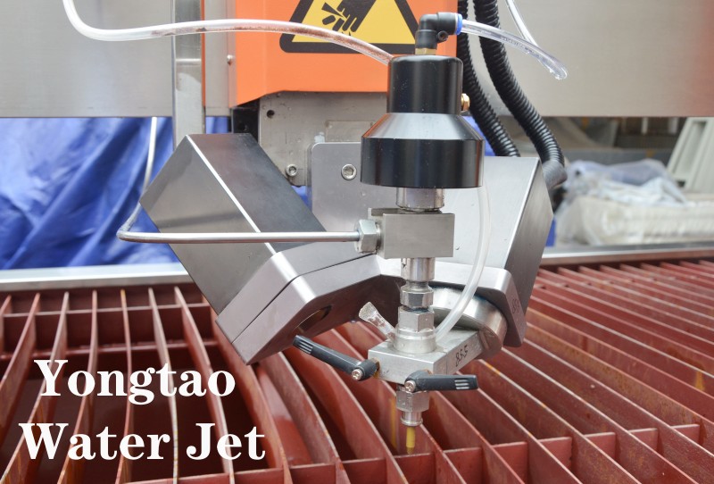
Orifice and focusing-tube combination
Nozzle wear
Standoff distance
Cutting-head alignment
Required edge-quality level
Nominal nozzle dimensions alone are not sufficient for precision pattern work.
For the offset principles used on internal and external profiles, see our detailed waterjet kerf compensation guide.
Begin with a clean vector drawing of the finished parquet, mosaic, medallion or inlay. The file should contain closed contours without duplicated lines, overlapping entities, short disconnected segments or accidental gaps.
Inspect the design for:
Sharp internal corners
Thin projections
Narrow bridges
Small holes
Closely spaced contours
Very short curves
Fragile tips
Pieces that may be difficult to handle
A mathematically sharp internal corner cannot always be reproduced as a perfectly sharp physical corner because the cutting stream has a measurable width. Small features should be evaluated in relation to the effective kerf, material thickness and brittleness.
When a decorative feature is too fragile, the better solution may be to increase its width, add a small radius, divide it into another component or use a different assembly detail.
Multi-color patterns frequently use tiles from different batches or material categories. Each component should be assigned to a specific material, color, texture and visible-face direction.
The material map should record:
Material code
Color code
Tile or slab number
Visible face
Grain direction
Pattern direction
Actual thickness
Surface defects
Quantity required
Spare-piece quantity
This is especially important when the design contains mirrored components or directional veining. Two pieces can have the correct geometry but still appear wrong when their texture runs in opposite directions.
Photographing and numbering the original tiles before nesting can help operators reproduce the approved visual layout.
Divide the completed design into individual production components. Assign each piece a unique identifier that corresponds with the assembly drawing.
A practical identification code can include:
Panel number
Material code
Piece number
Orientation mark
Duplicate quantity
For example, a large lobby medallion may be divided into several transportable panels. Piece identification should show both the panel location and the position of the individual component.
Avoid using only sequential numbers without an assembly map. Similar-looking pieces can be reversed or installed in the wrong section even when every component is present.
Prepare a digital assembly drawing and, when practical, a printed reference sheet for the cutting and assembly areas.
Nesting arranges parts on the available tile surface to reduce waste while maintaining safe cutting and handling conditions.
Effective nesting should consider:
Tile dimensions
Surface defects
Texture and veining
Part orientation
Edge distance
Distance between contours
Piercing clearance
Cutting sequence
Fragile-piece support
Reusable offcuts
Maximum material utilization should not be the only objective. Placing contours too close together can weaken the remaining material, increase the risk of movement or leave insufficient room for stable piercing.
For highly visible materials, visual continuity may be more important than achieving the highest nesting percentage.
Compensation should be assigned according to whether a contour produces an external piece, an internal opening or a shared boundary.
For normal closed profiles:
External components require the jet-center path to be offset toward the waste side.
Internal openings require compensation in the opposite direction.
Shared or mating edges must include the required finished joint.
Mirrored parts must retain the correct visible-face orientation.
Do not apply one global offset automatically to every contour. Internal and external features have different compensation directions, while mating components may require an additional assembly allowance.
For critical patterns, cut two or more adjoining test pieces and measure the assembled joint. This gives more useful information than measuring one standalone profile.
Piercing introduces concentrated energy into a small area, making it one of the highest-risk stages when processing brittle tile.
Where the geometry permits, start the pierce in waste material and use a lead-in path that reaches the finished contour only after the stream becomes stable.
Piercing points should be kept away from:
Visible finished edges
Narrow tips
Small internal corners
Thin bridges
Existing cracks
Unsupported areas
Glaze defects
The appropriate piercing method depends on the material structure, thickness, surface layer and installed cutting system. A slower or controlled piercing routine may be required for brittle porcelain, glazed ceramic or selected sintered materials.
The first pierce in a new tile batch should be observed before unattended production begins.
The cutting sequence should preserve support for fragile components and limit unnecessary movement of the remaining material.
A practical sequence normally considers:
Internal contours before external profiles
Small details before the surrounding material becomes unstable
Fragile parts while adequate support remains
Cuts that minimize rapid travel across finished surfaces
A safe final cut that does not release or tilt the component unexpectedly
Small finished pieces can fall between support slats or move after separation. Appropriate supports, catch surfaces or retention methods may be required.
The operator should also check that clamps and supports remain outside the programmed path.
Use the same material type, thickness, surface orientation, nozzle setup, abrasive condition and support method intended for production.
The test should evaluate:
Outside dimensions
Internal dimensions
Effective kerf
Top-edge condition
Bottom-edge condition
Edge taper
Corner quality
Surface chipping
Joint width
Fit between adjoining pieces
Cutting stability
Handling strength
A representative test should contain at least one external profile, one internal feature if used in the design, one corner and two mating edges.
Record the approved settings instead of relying on operator memory. If the material batch, thickness or nozzle condition changes, revalidation may be necessary.
During production, keep the tile evenly supported and confirm that the visible face is loaded in the correct direction.
After cutting:
Remove each component carefully.
Clean abrasive residue from its edges and surface.
Check for cracks and glaze damage.
Confirm its identification number.
Compare its orientation with the assembly drawing.
Store it on a padded or suitable support.
Separate rejected and replacement pieces.
Do not stack fragile shapes without protection. Narrow sections may survive cutting but break during cleaning, transfer or storage.
Spare components should be produced for designs containing fragile or repeated pieces when the project allows it.
Arrange the clean pieces without permanent adhesive according to the assembly drawing.

The dry assembly should verify:
Overall pattern dimensions
Joint consistency
Color sequence
Texture direction
Piece orientation
Reference-line alignment
Local contact points
Missing components
Height differences
Border dimensions
Inspect the completed pattern from more than one direction. Small cumulative errors may not be visible when examining only individual joints.
If several adjacent joints are consistently too narrow or too wide, correct the digital compensation rather than manually grinding every component. Manual adjustment should be reserved for limited local corrections.
The selected backing and adhesive method should match the material, panel size, transport method and final installation requirements.
Before bonding:
Confirm that all pieces are clean and dry as required.
Protect the visible surface.
Recheck the panel orientation.
Prepare alignment references.
Apply adhesive consistently.
Avoid excessive material entering the visible joints.
Prevent small pieces from moving during placement.
Large designs may need to be divided into numbered panels that can be transported and installed separately. Panel boundaries should be planned so they do not interrupt important visual features unnecessarily.
Pressing helps keep the assembled pieces on one plane while the backing or adhesive develops sufficient strength.
The objective is controlled flatness, not maximum pressure.
Excessive or uneven pressure can:
Move small components
Change joint widths
Force adhesive through the joints
Damage fragile edges
Create local height differences
Make the panel difficult to clean
Use a flat pressing surface and distribute pressure evenly. Follow the curing requirements of the selected adhesive or backing system before moving the assembly.
Ceramic, porcelain, glazed tile and sintered materials do not respond identically. Internal porosity, glaze condition, density, residual stress and manufacturing defects can influence the cut.
New or unfamiliar material should be tested even when its nominal thickness matches a previously processed tile.
Excessive speed can increase lower-edge lag, taper and dimensional variation. Reducing speed may improve the result, but cutting unnecessarily slowly increases time and cost.
The correct setting is the fastest validated speed that still produces the required joint and edge condition.
Interrupted or irregular abrasive flow can change cutting energy and kerf consistency. Check for moisture, contamination, feed restriction and unstable delivery when edge quality changes unexpectedly.
Orifice or focusing-tube wear can change stream alignment and effective kerf. Precision pattern production requires regular consumable inspection and a new test when wear may have affected dimensions.
An unsuitable standoff distance or misaligned cutting stream can increase edge damage and kerf variation. Verify cutting-head condition before correcting the CAD file for what is actually a mechanical setup problem.
Uneven support allows the tile to vibrate, tilt or move. Support should remain stable beneath the important cutting area without interfering with the stream.
Three-axis flat cutting is suitable for most two-dimensional parquet pieces, floor medallions, curved borders, logos, wall inlays and mosaic patterns.
Angled cutting may be useful when the finished assembly requires tapered interfaces, selected bevels or compensation for visible joint behavior. However, additional axes do not automatically improve every tile pattern.
Choose the cutting method according to the finished joint:
Use flat cutting for standard two-dimensional patterns with conventional joints.
Consider angled cutting when a validated tapered interface is required.
Do not select a more complex process unless it solves a defined assembly problem.
This decision should be based on sample assembly results rather than machine-axis count alone.
Possible causes include excessive joint allowance, incorrect kerf compensation, worn consumables or components installed in the wrong positions.
Measure both the individual pieces and the complete assembly before changing the cutting file.
Check whether joint space was included in the drawing and whether external-profile compensation was applied in the correct direction.
Do not force tightly fitting pieces together because local stress may damage narrow sections.
Move the pierce into waste material where possible, increase the lead-in distance, review the piercing routine and check the material support.
Review cutting speed, material thickness, nozzle condition, stream alignment and edge-quality setting. The visible top edge alone does not describe the entire kerf.
Check reference lines, piece numbering, cumulative joint allowances and panel assembly order. Small repeated errors can become significant across a large medallion.
Measure actual material thickness, inspect adhesive distribution, confirm the pressing surface and check whether different materials were combined without thickness calibration.

Before packaging or installation, confirm:
Overall length and width meet the approved drawing.
Pattern centerlines and borders are aligned.
Joint widths are visually and dimensionally consistent.
Colors and textures follow the approved material map.
No component is missing, reversed or incorrectly numbered.
Visible edges are clean and acceptable.
The assembled surface meets the required flatness.
Adhesive or backing coverage is complete.
No loose component remains.
Panel divisions match the installation drawing.
Visible surfaces are protected.
Packaging supports fragile sections and corners.
Panel numbers remain visible after packing.
Inspection records should identify the project, material batch, cutting-file version, test-cut result, assembly date and inspector.
A repeatable pattern requires more than saving the CAD file. The production record should include:
Drawing revision
Material and batch
Actual thickness
Cutting-head configuration
Abrasive specification
Effective kerf measurement
Compensation values
Piercing method
Cutting-quality setting
Approved joint width
Piece-numbering plan
Assembly method
Inspection result
These records help reproduce approved work and make later troubleshooting more efficient.
Kerf compensation corrects for the material removed by the cutting stream so that a component remains close to its specified size. Joint allowance creates the intended space between adjacent components after assembly. Precision parquet work normally requires both controls.
Two or more mating pieces provide a more useful test because they reveal the actual assembled joint. A single piece can meet its own dimensions while still fitting poorly with neighboring components.
Not always. The cutting stream has a finite width, so internal corners normally retain a small radius. Extremely sharp or narrow details may need to be redesigned, divided into separate pieces or completed by another finishing method.
Different batches may vary in actual thickness, density, glaze condition, internal stress or surface flatness. Nozzle wear, abrasive condition and machine setup may also change the effective kerf. A representative test should be repeated when relevant conditions change.
Yes. Three-axis cutting is suitable for most flat parquet, mosaic, medallion, logo, curve and inlay components. Angled cutting is only necessary when the final design requires tapered joints, selected bevels or another defined edge geometry.
Use stable material support, place piercing points in waste areas where possible, select an appropriate piercing routine, maintain the correct standoff distance, inspect nozzle condition and validate the cutting speed using the actual tile.
They should first be cleaned, identified and inspected. A dry assembly should then verify joint width, orientation, color order, overall dimensions and surface height before permanent adhesive or backing is applied.
Divide it into clearly numbered panels based on the installation plan. Protect visible surfaces, support fragile edges, prevent panel flexing and include an assembly drawing showing the position and orientation of every panel.
Provide the finished dimensions, CAD drawing, material type, actual thickness, visible-face direction, color allocation, required joint width, quantity, edge-quality requirement, backing method and installation layout.
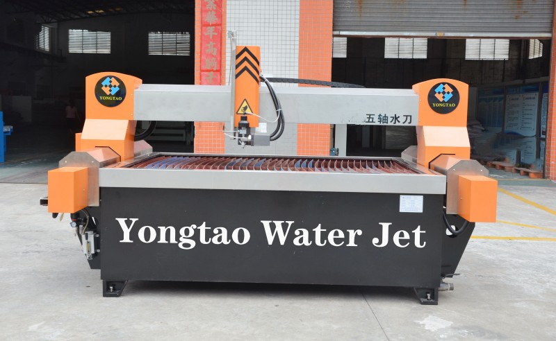
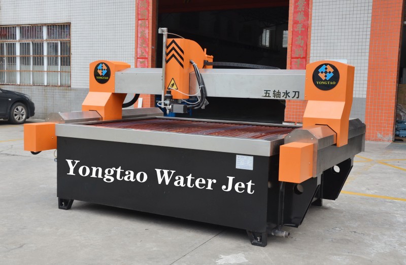
After the pattern geometry, material, joint requirements and production volume have been confirmed, buyers can review Yongtao’s Water Jet Tile Cutter configurations for ceramic tile, porcelain tile, parquet and mosaic processing.
This guide was reviewed from the perspective of CAD preparation, abrasive cutting, tile-piece identification, trial assembly and finished-pattern inspection. Final cutting and compensation values should always be validated using the actual material, thickness, nozzle condition, required joint and approved edge-quality standard.
0086-18665475362
[email protected]
Road 3, Wuzhuang Xiaofengtian Ind. Zone, Luocun Town, Nanhai Dist., Foshan, Guangdong, China