EN
Waterjet Cutting Pressure: Selection, Stability and Troubleshooting
Yongtao Machinery News and Technical Articles

Waterjet Cutting Pressure: Selection, Stability and Troubleshooting

  Jul 23-2026

Waterjet cutting pressure is one of the main variables that determines jet velocity and available cutting energy. It influences piercing performance, feed rate, cut-edge condition, abrasive utilization and the working load placed on high-pressure components.

Pressure, however, should never be treated as an isolated setting. The displayed value must be evaluated together with water flow, orifice diameter, mixing-tube condition, abrasive delivery, material thickness, feed rate and the required cut quality.

This guide explains how to select a practical operating pressure, identify pressure-related cutting problems and verify new settings through controlled trial cuts. It is intended for operators, process engineers, maintenance teams and production managers working with industrial abrasive waterjet systems.

Quick Answer: How Much Pressure Does Waterjet Cutting Require?

Industrial abrasive waterjet systems commonly operate within a broad range of approximately 210–620 MPa, or about 30,000–90,000 psi. The actual working range depends on pump design, available power, orifice size, component rating and the material-processing task.

Yongtao industrial systems are commonly configured for approximately 380–420 MPa, equivalent to about 55,000–61,000 psi, depending on the selected high-pressure pump and production requirements.

These figures are reference ranges rather than universal cutting settings. Operators must follow the rated limits and operating instructions supplied with the installed pump, tubing, fittings, valves and cutting head. Pressure must never be increased beyond the rating of the lowest-rated component in the high-pressure circuit.

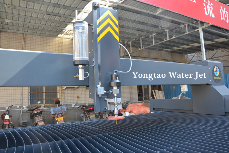
waterjet cutting pressure guide

Waterjet Pressure Conversion: MPa, Bar and PSI

Pressure specifications may be shown in MPa, bar or psi. Using the correct conversion prevents incorrect setup and makes it easier to compare pump specifications.

1 MPa is approximately 10 bar.

1 MPa is approximately 145 psi.

400 MPa is approximately 4,000 bar or 58,000 psi.

420 MPa is approximately 4,200 bar or 60,900 psi.

Pressure shown on the pump display is not always identical to the effective pressure available at the orifice. Component condition, leakage, pressure pulsation, line restrictions and control-system calibration can affect the energy delivered to the cutting head.

What Pressure Actually Does During Cutting

The high-pressure pump forces filtered water through a very small orifice. The pressure energy is converted into a high-velocity water stream. In abrasive cutting, this stream enters the mixing chamber, draws in abrasive particles and accelerates them through the mixing tube.

The abrasive particles perform most of the material removal when processing metals, stone, ceramic, glass and other hard materials. The water stream supplies the energy required to accelerate and direct those particles.

This means that increasing pump pressure does not automatically produce a proportional improvement at the workpiece. Effective cutting depends on the complete energy-transfer path:

  • Stable pump output

  • Correctly sized orifice

  • Undamaged jewel orifice

  • Proper alignment through the mixing chamber

  • Consistent abrasive metering

  • Suitable mixing-tube diameter and length

  • Correct standoff distance

  • Appropriate feed rate and pierce method

Energy can be lost at any stage, even when the pressure display appears normal.

Pressure, Flow Rate and Pump Power Must Be Evaluated Together

Pressure describes the force applied to the water, while flow rate describes the volume of water delivered over time. Pump power limits the combination of pressure and flow that the system can produce.

At a fixed power level, increasing pressure usually requires a change in flow or orifice size. Installing a larger orifice without confirming pump capacity can cause the system to operate below the intended pressure. Installing an unsuitable smaller orifice may restrict available flow and change the abrasive-loading requirement.

The practical question is therefore not simply, “What is the highest pressure?” It is:

“What pressure and flow combination can the installed pump maintain continuously with the selected orifice and abrasive rate?”

Continuous working pressure and pressure stability are more useful production indicators than a short peak value reached while the cutting head is closed.

How Pressure Influences Cutting Performance

Cutting Speed

Higher pressure generally increases jet velocity and can provide more cutting energy. When the entire system is correctly matched, this may allow a faster feed rate for the same material and target edge quality.

The speed increase must be verified by trial cutting. If feed rate is raised beyond the available cutting energy, the lower part of the cut may show heavy striations, excessive jet lag or incomplete separation.

Cut-Edge Quality

Stable pressure helps maintain consistent jet energy along the cutting path. Pressure loss or repeated pulsation may produce alternating smooth and rough sections, irregular striations or variation between the top and bottom of the cut.

Pressure is only one possible cause. Similar defects may result from incorrect speed, poor abrasive delivery, a worn orifice, damaged mixing tube, incorrect standoff distance or loose material.

Kerf and Taper

Pressure can affect jet coherence, material-removal rate and the relationship between the upper and lower kerf. It should not be used as the only method for correcting taper.

Feed rate, nozzle condition, mixing-tube alignment, standoff distance and cutting-head angle also affect taper. On compensated cutting systems, pressure and speed must remain sufficiently stable for the CNC taper-control strategy to work consistently.

Abrasive Utilization

Abrasive flow must be matched with water flow and available jet energy. Too little abrasive may reduce cutting capacity. Excessive abrasive can increase cost, accelerate mixing-tube wear and reduce acceleration efficiency when the particles interfere with one another.

Abrasive rate should therefore be optimized per finished part or per acceptable cut length, rather than judged only by kilograms consumed per hour.

Component Wear

Operating at higher pressure increases the load placed on seals, check valves, cylinders, high-pressure tubing, fittings, on/off valves and the cutting head. The actual wear rate depends on component design, water quality, operating hours, pressure cycling and maintenance condition.

A higher nominal pressure may reduce cutting time, but it may also increase maintenance demand. The correct comparison is total production cost per acceptable part, including abrasive, power, consumables, downtime and rejected workpieces.

How to Select a Practical Working Pressure

There is no universal pressure chart that can replace test cutting. A reliable pressure-setting decision should consider the following factors.

Material Type

Hard metals generally require abrasive cutting with sufficient and stable energy. Stone, ceramic and glass require particular attention during piercing because sudden full-pressure impact can initiate cracks, chips or delamination.

Soft materials cut with pure water may use a different nozzle configuration and should not be assigned abrasive-cutting parameters without process verification.

Material Thickness

Thicker material increases the distance through which the jet must retain useful energy. Cutting thick sections may require a slower feed rate, suitable abrasive delivery and a well-maintained cutting head.

Thickness alone does not determine pressure. A lower-pressure system may still separate a thick workpiece at a reduced speed, while a higher-pressure system may improve productivity when its flow, power and consumables are properly matched.

Required Edge Quality

A rough separation cut and a finished production edge have different requirements. If the part will be machined after cutting, a faster feed rate may be acceptable. If the cut edge must be used directly, the process may require a slower speed and closer inspection of taper, striation and dimensional error.

Production Volume

For occasional cutting, the highest available production rate may not justify increased wear. For repeat orders, a stable parameter set that reduces cycle time without increasing reject rate may provide a better total result.

Pump and High-Pressure Circuit Rating

The pump, accumulator, tubing, swivels, fittings, valves and cutting head must all be rated for the intended pressure. Never assume that replacing the pump alone allows the rest of the system to operate at a higher pressure.

Recommended Starting Strategy by Application

The following guidance describes adjustment priorities, not universal machine settings.

Metal Plate

Begin within the pump manufacturer’s approved working range. Confirm stable abrasive delivery and full penetration before increasing feed rate. Inspect the bottom edge for jet lag, heavy striation and incomplete separation.

For thicker metal, first verify orifice condition, abrasive consistency and nozzle alignment. Do not assume that every slow cut is caused by insufficient pressure.

Granite, Marble and Engineered Stone

Use controlled piercing and secure material support. On brittle or crack-sensitive stone, an edge start, pre-drilled entry hole or reduced-pressure pierce may be more appropriate than stationary full-pressure piercing.

After penetration, working pressure and speed can be increased gradually while monitoring chipping, lower-edge breakout and surface vibration.

Ceramic and Sintered Stone

Focus on piercing strategy, support condition and cutting sequence. A suitable pressure setting cannot compensate for an unsupported slab, unstable workpiece or poorly selected pierce point.

Trial cuts should include internal openings and corners because these locations may respond differently from a straight edge cut.

Glass

Use a verified low-impact piercing method. Depending on equipment capability and glass type, this may involve reduced-pressure piercing, dynamic piercing, an edge start or a pre-drilled entry point.

Do not apply general glass settings to tempered glass. Tempered glass normally cannot be conventionally cut after tempering without shattering.

Laminates and Composite Materials

The main risk may be delamination rather than lack of cutting power. Reduced-pressure or moving piercing can decrease the initial impact at one location. The final method should be validated on representative material because bonding systems and layer structures vary.

Practical Pressure Evaluation in Factory Testing

During factory testing, Yongtao evaluates working pressure as part of the complete cutting process rather than as an isolated display value. The test procedure may include pressure observation during continuous cutting, nozzle and abrasive-delivery inspection, representative material trials, and cut-edge evaluation.

For a new application, customers should provide the material name, thickness, part drawing, required edge quality and expected production volume. These details help determine whether the initial test should focus on pressure stability, feed rate, abrasive flow, piercing strategy or nozzle configuration.

Final cutting parameters should be confirmed using the customer’s actual or representative material. Results obtained from one material grade, thickness or surface condition should not automatically be applied to another production task.

Why Pressure Stability Matters More Than a Peak Reading

A pump may briefly reach the target value but fail to maintain it during a complete cutting cycle. This can create inconsistent results between straight lines, corners, pierces and long continuous paths.

Pressure stability should be evaluated while the cutting head is open and the system is cutting, not only while the pump is building pressure.

Check for:

  • Repeated rising and falling of the pressure display

  • Irregular intensifier cycling

  • Delayed recovery after the cutting head opens

  • Pressure loss during long cuts

  • Visible water leakage

  • Hydraulic-oil temperature outside the recommended range

  • Unusual vibration, knocking or valve noise

  • Cut quality changing along one continuous path

Record both the set pressure and observed working-pressure behavior. A single number does not describe whether the system is stable.

Waterjet Pressure Troubleshooting Guide

The System Cannot Reach the Set Pressure

Possible causes include:

  • Insufficient inlet-water supply

  • Blocked or contaminated water filter

  • Worn high-pressure seals

  • Leaking check valve

  • Water leakage from tubing, fittings or the cutting head

  • Incorrect orifice size

  • Damaged jewel orifice

  • Hydraulic-pressure problem

  • Pump-control or sensor error

  • Pump capacity that does not match the installed orifice

First isolate whether the problem is on the water-supply side, hydraulic side, high-pressure circuit or cutting-head side. Do not compensate for leakage or worn components by increasing the commanded pressure.

Pressure Reaches the Target but Fluctuates

Possible causes include:

  • Air entering the inlet-water circuit

  • Restricted inlet-water flow

  • Worn inlet or outlet check valves

  • Seal leakage

  • Irregular intensifier reversal

  • Hydraulic-oil temperature problems

  • Faulty accumulator or attenuator condition

  • Unstable control signal

  • Intermittent high-pressure leakage

Compare the fluctuation pattern with the pump cycle. A regular change linked to intensifier reversal suggests a different inspection path from a random pressure drop occurring only during cutting.

Pressure Appears Normal but Cutting Power Is Low

Possible causes include:

  • Chipped or worn orifice

  • Poor alignment between the orifice and mixing tube

  • Worn or oversized mixing tube

  • Blocked or inconsistent abrasive delivery

  • Damp or contaminated abrasive

  • Incorrect abrasive rate

  • Excessive standoff distance

  • Feed rate set too high

  • Incorrect nozzle combination

  • A pressure gauge or sensor that requires verification

Inspect the complete cutting head and abrasive path before concluding that a larger pump or higher pressure is necessary.

Pressure Drops When the Cutting Head Opens

A small change may occur as water begins flowing, but a large or persistent drop requires investigation.

Check whether the pump has enough capacity for the installed orifice. Then inspect inlet-water supply, filters, seals, check valves, leakage points and the accuracy of the pressure reading.

Seals Fail Too Frequently

Frequent seal failure may be associated with:

  • Contaminated or improperly treated inlet water

  • Incorrect assembly

  • Damaged sealing surfaces

  • Pressure cycling

  • Operating temperature problems

  • Misaligned components

  • Operation above the component rating

  • Delayed replacement of related worn parts

Replacing only the failed seal without identifying the operating cause may lead to repeated downtime.

A Controlled Method for Optimizing Pressure

Pressure optimization should change one variable at a time while the remaining conditions are recorded.

Step 1 — Establish a Baseline

Record:

  • Material name and grade

  • Material thickness

  • Pump model

  • Set and observed working pressure

  • Orifice size

  • Mixing-tube size

  • Abrasive type and mesh

  • Abrasive flow rate

  • Standoff distance

  • Pierce method and time

  • Feed rate

  • Target cut quality

Step 2 — Inspect the System Before Testing

Confirm that filters, orifice, mixing tube, abrasive hose, metering device and high-pressure connections are in serviceable condition. Parameter testing performed with worn components produces misleading results.

Step 3 — Make a Representative Test Cut

A useful test coupon should include:

  • A straight cut

  • An internal corner

  • An external corner

  • A small hole or internal contour

  • The intended piercing method

  • Sufficient cut length to reveal pressure instability

Step 4 — Inspect the Entire Cut

Evaluate the upper and lower kerf, striation direction, taper, corner condition, piercing damage, dimensions and completeness of separation.

Do not judge the result from the top surface alone.

Step 5 — Change One Variable

If pressure is being evaluated, keep the orifice, abrasive rate, feed rate and standoff distance unchanged for the first comparison. After identifying a stable pressure range, optimize speed and abrasive delivery separately.

Step 6 — Calculate the Result per Acceptable Part

Compare:

  • Cutting time

  • Abrasive consumption

  • Power use

  • Consumable wear

  • Rework

  • Rejected parts

  • Operator intervention

  • Unplanned downtime

The most economical setting is the one that consistently produces acceptable parts at the lowest total production cost—not necessarily the lowest abrasive rate or highest pressure.

Pressure Adjustment Safety

Ultra-high-pressure water can penetrate skin, damage equipment and release stored energy unexpectedly. Pressure-related inspection and maintenance must be performed only by trained personnel.

A scheduled inspection of high-pressure tubing, fittings and connections can help maintenance teams identify leakage, surface damage, abnormal vibration and connection problems before pressure testing or production.

Before servicing the high-pressure circuit:

  • Stop the pump according to the approved procedure

  • Confirm that stored pressure has been released

  • Lock out the relevant energy sources

  • Never search for a leak with bare hands

  • Replace damaged tubing and fittings with correctly rated parts

  • Follow the pump and component manufacturer’s torque requirements

  • Never mix unidentified or incompatible high-pressure components

  • Keep personnel away from the cutting head during pressure testing

A suspected high-pressure injection injury requires immediate emergency medical evaluation, even when the external wound appears small.

Pressure Setting Record for Repeat Production

For repeat orders, keep a controlled parameter record containing:

  • Part or drawing number

  • Material supplier and grade

  • Thickness

  • Pressure setting

  • Observed pressure stability

  • Orifice and mixing-tube combination

  • Abrasive specification and flow

  • Pierce method

  • Cutting speed by quality level

  • Standoff distance

  • Inspection results

  • Consumable condition

  • Date and operator

When a repeat job produces a different result, compare the current setup with this record before making random adjustments. This shortens troubleshooting time and helps different operators reproduce the same process.

When a Pressure Problem Is Actually a Process Problem

Not every cutting defect should be corrected by changing pressure.

If the top edge is acceptable but the bottom edge shows strong lag lines or visible waterjet cut surface striations, the feed rate may be too high or the available cutting energy may be insufficient.

If rough and smooth sections alternate, check pressure stability and abrasive consistency.

If the kerf becomes wider and accuracy declines, inspect the orifice and mixing tube.

If brittle material cracks during entry, revise the piercing method and material support.

If cutting performance declines gradually, inspect consumable wear and abrasive quality.

If dimensions are incorrect but the edge remains consistent, check calibration, backlash, motion control and workpiece movement.

A symptom-based diagnosis prevents unnecessary pressure increases and reduces the risk of hiding the actual fault.

Technical Summary

Waterjet cutting pressure determines part of the energy available to accelerate the cutting stream, but pressure alone does not determine productivity or quality.

A reliable process requires:

  • A pressure and flow combination matched to pump power

  • An orifice suitable for the installed pump

  • Stable pressure under continuous cutting load

  • Consistent abrasive delivery

  • A correctly aligned and serviceable cutting head

  • A feed rate matched to material and edge-quality requirements

  • A suitable piercing method for brittle or laminated materials

  • Parameter records verified by representative trial cuts

The correct setting is the lowest practical combination of pressure, abrasive use and cycle time that repeatedly meets the required quality while keeping the high-pressure system within its rated operating limits.

Frequently Asked Questions

How much pressure is normally used for abrasive waterjet cutting?

Industrial abrasive systems may operate from approximately 210 to 620 MPa, or about 30,000 to 90,000 psi. The correct working pressure depends on pump design, power, orifice size, component rating and the cutting task. Yongtao industrial configurations commonly use approximately 380–420 MPa, depending on the selected pump and application.

Is higher waterjet pressure always better?

No. Higher pressure may improve jet velocity and cutting speed when the pump, orifice, abrasive rate and cutting head are properly matched. It can also increase component stress and maintenance requirements. Total cost per acceptable part is a more useful measure than pressure alone.

Why is the displayed pressure correct but the cut is still weak?

Possible causes include a damaged orifice, worn mixing tube, poor nozzle alignment, inconsistent abrasive feed, damp abrasive, excessive standoff distance or excessive feed rate. The pressure sensor may also require verification.

What causes waterjet pressure to fluctuate?

Common causes include restricted inlet water, air in the supply, worn seals or check valves, irregular intensifier cycling, hydraulic-temperature problems, leakage, accumulator problems or an unstable control signal.

Should thick material always be cut at maximum pressure?

Not necessarily. Thick material requires enough cutting energy, but feed rate, abrasive flow, nozzle condition and target edge quality are equally important. A stable lower-pressure process may cut the material at a slower speed, while a higher-pressure process may improve productivity if the system is properly matched.

Can pressure be reduced when piercing glass or stone?

Yes. Reduced-pressure, dynamic, edge-start or pre-drilled piercing may reduce the initial impact on some fragile materials. The correct method depends on equipment capability, material structure and support condition and should be confirmed through testing.

Why does pressure fall when the cutting head opens?

The pump begins supplying flow through the orifice when the head opens. A substantial pressure drop may indicate insufficient pump capacity for the orifice, inadequate inlet-water supply, worn seals or valves, leakage, filter restriction or an inaccurate reading.

How often should pressure settings be checked?

Check the displayed and observed working pressure at the start of production, after changing the orifice or mixing tube, after maintenance, and whenever cut quality changes. Repeat jobs should be compared with a documented baseline.

Can abrasive flow be increased instead of raising pressure?

Sometimes, but only within the effective range for the water flow and nozzle combination. Too little abrasive limits cutting capacity, while excessive abrasive may reduce acceleration efficiency, increase wear and raise cost. Adjustments should be verified through controlled tests.

What is the safest way to investigate a high-pressure leak?

Stop the equipment, isolate energy and release stored pressure according to the approved procedure. Never use a bare hand to locate a leak. Inspection and replacement must be carried out by trained personnel using correctly rated components.

Conclusion

Effective waterjet pressure control is based on stability, system matching and verified production results. Operators should evaluate pressure together with flow, orifice size, abrasive delivery, feed rate, piercing method and consumable condition.

By recording baseline parameters, inspecting the complete energy-transfer path and changing one variable at a time, manufacturers can improve cutting consistency without relying on unnecessary pressure increases. This approach supports predictable quality, safer operation and more accurate control of production cost.

For manufacturers that have already confirmed their pressure, material and production requirements, Yongtao provides different industrial waterjet system configurations for application testing and equipment comparison.


Contact Us