
Abrasive waterjet first-part inspection is a controlled process used to verify that a new or modified cutting setup can produce a part that meets the drawing, material, dimensional and edge-quality requirements before batch production begins.
The validation process normally includes drawing review, material confirmation, toolpath verification, a dry run, representative test cutting, dimensional inspection, edge assessment and documented approval. If the first part does not meet the acceptance criteria, the cause should be identified and one process variable adjusted at a time.
The purpose of first-part validation is not simply to confirm that the jet can cut through the material. It verifies that the complete production method can repeatedly deliver conforming parts while controlling cutting time, abrasive consumption, consumable wear and rework risk.
An abrasive waterjet process should be validated in the following order before batch production:
Confirm the drawing revision and required tolerances.
Identify the material type, thickness and surface condition.
Define critical features and acceptable edge quality.
Check the usable cutting area and supporting slats.
Select part orientation, spacing and holding points.
Place pierces, lead-ins and lead-outs outside critical edges.
Choose a starting parameter set from verified process records.
Perform a dry run with the high-pressure jet disabled.
Cut a representative test coupon or first part.
Inspect dimensions, taper, striation, chipping and surface condition.
Adjust one process variable at a time when correction is required.
Record the approved settings before releasing batch production.
This sequence reduces guesswork and makes the final process easier to repeat across operators, shifts and future orders.

Machine operation describes how to start, run and stop the equipment safely. Job setup answers a different question: how should a specific drawing and material be converted into an approved cutting process?
Two jobs performed on the same system may require different:
piercing methods;
lead-in positions;
traverse speeds;
abrasive flow settings;
standoff distances;
cut-quality selections;
workholding arrangements;
cutting sequences;
dimensional allowances;
inspection methods.
The process should therefore be based on the production task instead of a general rule such as “use higher pressure” or “reduce speed.” Changing parameters without identifying the actual defect can increase cutting time without correcting the source of the problem.

The operator or process engineer should collect the necessary production information before preparing the cutting path.
Confirm:
drawing number;
drawing revision;
quantity;
material specification;
nominal thickness;
dimensional tolerances;
angular tolerances;
edge-finish requirements;
important datum surfaces;
downstream machining operations;
protected or cosmetic surfaces;
required inspection records.
If the drawing does not specify the required edge quality, clarify whether the cut is intended for separation, direct assembly, welding, polishing or secondary machining. A rough separation cut and a visible finished edge should not be programmed with the same quality target.
Record the actual material rather than relying only on a general category such as metal, stone or glass.
Important material details include:
material grade or commercial name;
measured thickness;
hardness or density where relevant;
laminated or monolithic construction;
brittle, porous or reinforced structure;
protective film or surface coating;
grain, pattern or decorative direction;
pre-existing cracks, voids or edge damage;
flatness and surface variation;
batch identification.
Material differences can change piercing behavior, cutting speed and edge quality. A process previously verified for one batch should be reviewed when the thickness, composition or surface condition changes.
Drawing review helps identify features that may require a special cutting strategy.
Mark dimensions that affect assembly, sealing, alignment or later machining. These features should receive the highest inspection priority.
Examples include:
hole diameter and position;
slot width;
distance between features;
outside profile dimensions;
mating edges;
corner locations;
bevel angle;
countertop openings;
reference datums.
Do not assume that every dimension requires the same process quality. Applying the slowest cut setting to the entire part may increase production time without improving the features that matter.
The achievable internal radius depends partly on the effective jet diameter and toolpath compensation. A drawing containing an internal corner smaller than the practical cutting radius may require a design change or secondary operation.
Narrow slots and closely spaced features should also be reviewed for:
jet overlap;
remaining material strength;
heat-free but mechanically aggressive piercing;
small pieces falling into the tank;
movement during the final contour;
dimensional change caused by worn consumables.
Finished edges may require slower movement, better taper control or secondary finishing. Trim edges and sacrificial areas may accept faster cutting.
Classifying the edges before programming allows the operator to assign process quality according to function rather than using one setting for the entire drawing.
A correct program can still produce poor parts when the material is unsupported, uneven or able to move.
Measure the material at several positions when thickness variation is possible. The cutting database should use the actual production thickness, not only the nominal value shown on the purchase document.
Thickness affects:
pierce time;
cutting speed;
jet lag;
edge striation;
taper;
risk of incomplete penetration.
Worn, bent or uneven slats can allow the workpiece to tilt. A previously cut slat may also place a gap directly under a small feature or pierce point.
Before loading the material:
remove loose fragments;
check for unstable support;
confirm that the sheet or slab sits flat;
avoid placing critical pierces over large unsupported gaps;
replace or reposition unsuitable slats when necessary.
Heavy material may remain stable through its own weight, but small, thin or narrow pieces may move when the jet completes the contour.
Depending on the task, movement can be controlled through:
suitable clamps outside the toolpath;
weights approved for the application;
tabs or micro-joints;
bridges between small parts;
cutting sequence changes;
sacrificial cover sheets;
a supporting fixture.
Clamps and weights must never be placed where the cutting head, bridge or high-pressure stream can contact them.
The best layout is not always the layout containing the largest number of parts. The arrangement must also support stable cutting and safe removal.
Consider:
material grain;
visible pattern;
rolling direction;
finished surface direction;
expected taper direction;
downstream machining datums;
part handling after cutting.
Decorative stone, ceramic and patterned slabs may require visual alignment that is more important than maximum material utilization.
In most jobs, holes, slots and internal openings should be completed before the outside contour. Once the outside profile is released, the part may shift and reduce the accuracy of remaining features.
Exceptions should be evaluated according to material stability, fixture design and the risk of small cutouts interfering with later toolpaths.
Thin bridges, pointed corners and narrow sections should not be released too early. Plan the sequence so that the surrounding material supports these features for as long as practical.
The operator should also consider whether a cutout may tip, float or interfere with the nozzle after separation.
Piercing is often more demanding than steady cutting because the initial jet energy is concentrated at one location.
Whenever the drawing allows it, place the pierce in scrap material and connect it to the profile through a lead-in. This prevents the initial pierce mark from becoming part of the finished edge.
Pierce points should be kept away from:
visible finished edges;
narrow sections;
corners;
existing cracks;
unsupported areas;
laminate boundaries;
decorative surfaces that cannot be repaired.
A lead-in should give the jet enough distance to complete the pierce and enter the required profile under stable conditions.
The suitable lead-in shape depends on the material, thickness, kerf, geometry and control software. Straight, angled, arc and loop lead-ins may all be appropriate in different situations.
The operator should verify that the lead-in:
remains inside scrap material;
does not cross another toolpath;
avoids a clamp or support;
provides enough room for the selected pierce method;
enters the finished contour smoothly.
Brittle, laminated or easily delaminated materials may be damaged by a full-energy stationary pierce. Depending on equipment capability and material response, possible approaches include:
low-pressure piercing;
dynamic or moving piercing;
circular piercing;
vacuum-assisted piercing;
pre-drilled starting holes;
piercing outside the finished part;
using a sacrificial cover layer.
The correct method should be confirmed through a representative test. Tempered glass should not be treated as ordinary annealed glass because its internal stress condition makes conventional profile cutting unsuitable.
A starting process should come from manufacturer data, CAM software, verified job records or controlled testing. It should not be copied blindly from an unrelated material.
The starting record should include:
material specification;
actual thickness;
pump pressure;
orifice size;
mixing-tube size;
abrasive type;
abrasive mesh;
abrasive flow rate;
standoff distance;
pierce method;
pierce time;
traverse speed;
selected cut-quality level;
compensation value;
nozzle condition.
Pressure, speed, abrasive delivery and nozzle geometry operate as a system. Changing one value can affect other parts of the process.
Higher pressure can increase available cutting energy, but it does not automatically correct:
a worn mixing tube;
unstable abrasive delivery;
excessive standoff;
an incorrect toolpath offset;
loose material;
poor piercing placement;
a damaged orifice;
unsuitable edge-quality selection.
Use a stable pressure supported by the system configuration and verified process data. Pressure stability during the cut is more useful than a high peak reading that fluctuates.
Abrasive mesh should be selected together with the orifice, mixing tube, material and required finish. Finer abrasive may improve the surface in some applications, but it may also change feed behavior and cutting performance.
Before production, confirm that the abrasive is:
dry;
clean;
free from oversized particles;
compatible with the feed system;
flowing consistently;
stored away from moisture.
This page should not prescribe one universal mesh size because the correct selection depends on the complete cutting-head combination and production objective.
A dry run allows the operator to verify motion without activating the cutting stream.
Check:
program origin;
X- and Y-axis direction;
material boundaries;
nozzle clearance;
clamp positions;
lead-in and lead-out locations;
cutting-head travel;
collision risk;
toolpath sequence;
return and parking positions.
For a large or expensive workpiece, the operator may run the program above the surface at reduced movement speed. Stop immediately if the path approaches a clamp, material edge or prohibited area.
A test coupon should reproduce the difficult parts of the real job. A simple straight line may not reveal problems that appear in holes, corners or closely spaced features.
A useful coupon may include:
an outside contour;
an internal hole;
a narrow slot;
an inside corner;
an outside corner;
a short lead-in;
the intended pierce method;
a feature aligned in each major cutting direction.
Use material from the same specification and similar thickness as the production workpiece. Record all starting parameters before cutting so that the result can be traced.
Inspection should compare the result with defined acceptance criteria instead of relying only on visual appearance.
Measure the features that are important to assembly or downstream processing.
Depending on the part, inspect:
overall length and width;
hole diameter;
hole position;
slot width;
distance between features;
corner location;
diagonal dimensions;
bevel angle;
top and bottom dimensions.
Use calibrated measuring equipment suitable for the tolerance and material. Soft, brittle or irregular materials may require a different inspection method from machined metal components.
Inspect both the top and bottom of the cut.
Look for:
excessive taper;
pronounced lower-edge striation;
incomplete penetration;
top-edge rounding;
bottom-edge burr or attached material;
chipping;
delamination;
surface staining;
excessive kerf width;
inconsistent finish around corners.
A smooth top edge does not prove that the complete cut is acceptable. Jet lag and energy loss are often more visible near the lower section of thicker material.
If one side of a square measures differently from another, the problem may involve compensation, machine geometry, nozzle alignment or directional behavior rather than cutting speed alone.
Inspecting features in both axes helps separate a global parameter problem from a directional accuracy problem.
When the first part does not meet the acceptance criteria, confirm the drawing, material, workholding, nozzle condition, abrasive delivery, pressure stability, standoff distance and compensation before changing the process. Adjust only one variable at a time and produce another controlled sample. Detailed troubleshooting procedures should remain separate from the first-part validation record so that the cause, correction and inspection result can be traced clearly.
The first production part should be formally reviewed when the order contains critical dimensions, expensive material or a large quantity.
The approval record should identify:
job number;
drawing revision;
material batch;
program version;
machine identification;
operator;
date;
verified parameters;
measuring equipment;
measured results;
visual findings;
corrections made;
approval status.
Batch production should begin only after the first part meets the defined requirements or the customer-approved acceptance criteria.
| Record Item | Information to Confirm |
|---|---|
| Job identification | Job number, drawing number and revision |
| Material | Grade, supplier, batch and measured thickness |
| Program | CAM file and program version |
| Cutting setup | Pressure, speed, abrasive and nozzle combination |
| Piercing | Pierce method, location and time |
| Workholding | Clamps, supports, tabs or fixtures |
| Inspection | Critical dimensions, taper and edge condition |
| Measuring tools | Tool identification and calibration status |
| Result | Accepted, adjusted or rejected |
| Approval | Operator, inspector, date and notes |
A reusable job record is more valuable than an isolated parameter value.
Store:
final CNC or CAM file;
drawing revision;
material and thickness;
nozzle combination;
abrasive specification;
pressure and flow settings;
pierce method;
speed or quality selection;
compensation value;
fixture arrangement;
material origin;
photographs of the setup;
inspection results;
operator notes;
consumable condition.
When the job is repeated, compare the current material and machine condition with the approved record before reusing the parameters.
A previously approved process should be reviewed when a change could affect the dimensions, edge quality, piercing behavior or repeatability of the finished part.
Revalidation may be required after:
a drawing or tolerance revision;
a material grade, thickness or supplier change;
replacement of the orifice, mixing tube or cutting head;
a change in abrasive type or mesh;
modification of pressure, cutting speed or compensation;
movement of the work origin or fixture;
transfer of the job to another machine;
a long interruption in production;
repeated dimensional drift or edge-quality defects;
a customer request for renewed first-part approval.
The level of revalidation should match the risk of the change. A minor consumable replacement may require a representative dimensional and edge-quality check, while a new material or revised drawing may require complete first-part inspection.
Before cutting:
Confirm the latest drawing revision.
Verify material type, thickness and batch.
Identify critical dimensions and visible edges.
Inspect the cutting table and supporting slats.
Confirm the material is flat and stable.
Position clamps outside all toolpaths.
Check pierce locations and lead-ins.
Confirm nozzle clearance and standoff.
Load an appropriate verified starting process.
Complete a dry run.
During validation:
Cut a representative coupon or first part.
Observe pressure and abrasive delivery.
Check for movement during contour release.
Inspect the top and bottom edges.
Measure critical features.
Adjust only one variable at a time.
Repeat the test when a process change is made.
Before batch production:
Approve the first part.
Save the final program version.
Record the approved settings.
Define an inspection frequency.
Confirm safe unloading and part identification.
Retain the process record for repeat orders.
First-part approval does not eliminate the need for continued monitoring. Consumable wear, material variation and handling conditions can change during a long production run.
The inspection frequency should reflect:
order quantity;
tolerance;
material value;
process stability;
consumable life;
consequence of a rejected part;
customer requirements.
At minimum, compare parts at planned intervals and after any nozzle replacement, abrasive interruption, pressure alarm, program adjustment or material batch change.
Stop the job when a progressive dimensional change or new edge defect appears. Continuing production without identifying the cause may convert a small process problem into an entire rejected batch.
Professional abrasive waterjet job setup combines drawing review, material assessment, toolpath planning, controlled parameter selection and measurable first-part approval.
The most dependable process is not necessarily the one using the highest pressure or slowest cutting speed. It is the process that repeatedly produces conforming parts with controlled cutting time, abrasive use, consumable wear and inspection effort.
When a new material, thickness or geometry is introduced, begin with verified baseline data, perform a representative test and record the approved result. This creates a repeatable production method that can be reviewed, transferred and improved without depending entirely on an individual operator’s memory.
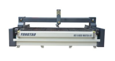
For companies evaluating equipment after confirming their process requirements, Yongtao provides complete industrial waterjet configurations for different materials, table sizes and axis requirements.
Abrasive waterjet first-part inspection is the verification of the first production part before batch cutting begins. It confirms that the drawing revision, material, toolpath, cutting parameters, dimensions and edge condition meet the defined acceptance requirements.
No. The process should use a stable pressure that matches the pump, cutting head, material and verified parameter set. Maximum pressure cannot correct worn consumables, poor abrasive flow, incorrect compensation or unstable workholding.
A representative coupon allows the operator to evaluate piercing, edge quality, taper, kerf and dimensions without risking the complete workpiece. It is especially useful for new materials, expensive slabs, critical tolerances and fragile components.
Check critical dimensions, feature positions, top and bottom kerf, taper, lower-edge striation, chipping, delamination, incomplete penetration and surface condition. The inspection should follow the drawing and agreed acceptance criteria.
Place the pierce in scrap material where possible. Depending on the material and equipment, use low-pressure, dynamic, circular or vacuum-assisted piercing, a pre-drilled hole or a sacrificial cover layer. Confirm the method through testing.
Possible causes include material movement, consumable wear, abrasive-flow variation, pressure instability, changing standoff distance, fixture movement, work-offset errors and thickness variation. Compare parts from different stages of the batch to determine whether the change is progressive or sudden.
No. Change one variable at a time whenever practical. This makes it possible to identify which adjustment corrected the problem and helps create a dependable process record.
Save the drawing revision, program version, material batch, actual thickness, nozzle combination, abrasive specification, pressure, speed, pierce method, compensation, fixture arrangement, inspection results and operator notes.
Not by itself. A more useful evaluation considers acceptable parts produced, cutting time, abrasive use, consumable wear, labor, material utilization, inspection and rework. A lower hourly cost does not help if the process produces fewer conforming parts.
Inspection frequency should be based on tolerance, order quantity, material value, process stability and customer requirements. Additional inspection should be performed after alarms, parameter changes, nozzle replacement, abrasive interruption or a material batch change.
 0086-18665475362
[email protected]
Road 3, Wuzhuang Xiaofengtian Ind. Zone, Luocun Town, Nanhai Dist., Foshan, Guangdong, China


YONGTAO Machinery is committed to becoming a trusted global manufacturer of innovative and reliable ceramic, stone, and waterjet cutting machinery. We strive to deliver high-quality equipment and professional solutions that enhance productivity, create lasting value for our customers, and build long-term success with our employees and global partners.
 0086-18665475362
 [email protected]
 Road 3, Wuzhuang Xiaofengtian Ind. Zone, Luocun Town, Nanhai Dist., Foshan, Guangdong, China
 English
 Español