Consistent waterjet cutting depends on more than increasing pressure or reducing cutting speed. Material condition, nozzle alignment, abrasive delivery, workpiece support, piercing method, cutting path and operator records all influence the finished edge.
The most effective approach is to check the process in a fixed order. Operators should first confirm that the machine and material are ready, then establish a stable baseline, inspect the first cut and adjust only the parameter connected to the observed defect.
This guide explains practical waterjet cutting tips for improving process stability, cut quality and production efficiency without relying on random parameter changes.
For more stable abrasive waterjet cutting, operators should:
Inspect the cutting head, high-pressure lines and abrasive supply before production.
Confirm material type, thickness, flatness and support conditions.
Use a suitable orifice and focusing tube combination.
Set cutting speed, pressure and abrasive flow as a coordinated group.
Keep the nozzle height stable across the cutting path.
Place piercing points and lead-ins away from critical finished edges.
Use controlled piercing methods for glass, ceramic, stone and laminated materials.
Secure small parts and prevent movement during cutting.
Inspect the first finished part before starting continuous production.
Record verified parameters so the same process can be repeated.
The best setting is not a single universal value. It is the combination that produces the required edge quality, accuracy and output for a specific material, thickness and part geometry.

A short inspection before production can prevent damaged parts, unstable cutting and unnecessary machine downtime. The purpose is not only to confirm that the machine can start. It is to establish whether all essential systems can deliver a stable process.
Operators should inspect the following items:
Water supply pressure and filtration condition
Hydraulic-oil or pump-system condition
High-pressure tubing, fittings and connection points
Orifice, mixing chamber and focusing tube condition
Abrasive level, abrasive dryness and delivery stability
Cutting-table slats and workpiece supports
Material position, flatness and clamping
Cutting-head movement and available clearance
CNC program, origin point and cutting-path direction
Cooling, air supply and other auxiliary systems
Leaks, unusual vibration, irregular pump cycling, damaged tubing, blocked abrasive delivery or a visibly worn nozzle should be addressed before cutting begins.
A machine may reach the displayed pressure and still produce inconsistent results if pressure delivery, abrasive flow or cutting-head alignment is unstable. Pre-cut inspection therefore focuses on operating consistency rather than one displayed value.
Material name alone is not enough to determine the cutting setup. Two slabs described as the same material may behave differently because of thickness, hardness, internal stress, surface coating, reinforcement or lamination.
Before programming the job, confirm:
Exact material type
Actual thickness
Maximum workpiece dimensions
Surface flatness
Presence of a coating, film or laminated layer
Required finished-edge quality
Dimensional tolerance
Hole size and narrow internal features
Whether the finished edge will remain visible
Number of identical parts required
Granite, marble, quartz, ceramic, glass, steel and aluminum do not respond identically to piercing and continuous cutting. Brittle materials require careful entry control, while thick materials require sufficient jet energy and an appropriate cutting speed through the full depth.
When the material or thickness is unfamiliar, perform a test cut on an offcut before processing the finished slab.
One of the most common process-control mistakes is changing pressure, speed, abrasive flow and nozzle height at the same time. Even if the result improves, the operator cannot identify which adjustment corrected the problem.
A more reliable method is:
Start with a previously verified parameter set for the same or a similar material.
Cut a short test profile containing a straight edge, corner and curve.
Inspect the top edge, lower edge, kerf, taper and striation pattern.
Identify the most important defect.
Adjust one relevant parameter.
Repeat the test and record the result.
Continue only until the required quality level is reached.
This one-variable method creates useful production data and reduces repeated trial and error. Over time, the factory can build a material-specific process library that includes thickness, pressure, speed, abrasive flow, nozzle combination, piercing method and achieved edge quality.
For repeatable process optimization, follow this order:
Confirm the material, thickness and finished-part requirements.
Inspect the cutting head, abrasive delivery, pressure stability and workpiece support.
Run a short test cut using a previously verified baseline.
Identify the dominant defect and adjust only one related variable.
Approve and record the final settings before batch production.
This sequence helps operators separate equipment problems from parameter problems and creates a clearer record for future production.
Cutting speed directly affects productivity, but the fastest setting is not always the most economical setting.
If the speed is too high, the lower part of the cut may show:
Heavy striations
Increased jet lag
Excessive taper
Poor corner definition
Incomplete penetration
Dimensional deviation
If the speed is unnecessarily low, cutting time and cost per part increase. Very slow cutting may also produce excessive material removal in some applications.
The correct speed should be selected according to the required finished condition. A hidden structural edge may not need the same surface quality as a visible decorative edge, countertop opening or precision inlay component.
Instead of applying the highest quality setting to every contour, operators can assign different quality levels to different features. Critical edges can use a slower finishing speed, while noncritical separation cuts can use a more productive setting.
Pressure and abrasive flow should be evaluated together with cutting speed, nozzle condition and material thickness.
A high displayed pressure does not automatically produce a clean edge. Frequent pressure fluctuation can change jet energy during the cutting path. Similarly, an unstable abrasive feed can cause alternating smooth and rough sections on the same edge.
Operators should check for:
Repeated pressure fluctuation during continuous cutting
Irregular pump cycling
Wet or contaminated abrasive
Abrasive bridging inside the hopper
Restricted or damaged abrasive hose
Worn metering components
Partial blockage in the mixing chamber
An incorrect abrasive feed rate
A worn or damaged focusing tube
Using more abrasive than necessary does not always increase cutting efficiency. Excessive abrasive can reduce mixing performance, increase consumption and accelerate component wear. An insufficient supply can reduce cutting power and make the lower edge rougher.
The objective is a steady abrasive flow that matches the orifice, focusing tube, pressure level, material and cutting speed.
The orifice creates the high-velocity water stream, while the focusing tube guides the water-abrasive mixture toward the workpiece. Their size, condition and alignment affect kerf consistency and cutting efficiency.
Typical signs of cutting-head wear or misalignment include:
A wider or irregular kerf
One-sided taper
Unstable jet shape
Reduced cutting performance
Rough sections appearing without a program change
Faster-than-normal abrasive consumption
Difficulty maintaining dimensional accuracy
Operators should not replace components only according to operating hours. Inspection should also be based on cutting behavior and measured part quality.
When installing an orifice or focusing tube, keep the contact surfaces clean and follow the component supplier’s assembly procedure. A new focusing tube cannot correct a damaged or misaligned orifice, and increased pressure cannot compensate reliably for a worn cutting head.
Nozzle height affects jet concentration, kerf width, edge quality and collision risk. The important principle is not simply using the smallest possible distance. The height must remain suitable and stable across the complete workpiece.
If the nozzle is too far from the surface, the jet may begin to spread before entering the material. This can increase top-edge erosion, kerf width, taper and visible striations.
If it is too close, an uneven or warped workpiece may contact the nozzle. Splashback and abrasive rebound may also accelerate wear.
Before cutting, check:
Material flatness
Support height
Slat condition
Cutting-head height setting
Height-sensing function, if equipped
Clearance around clamps and fixtures
Clearance during angled cutting
For detailed nozzle-distance diagnosis, operators should refer to the dedicated Waterjet Standoff Distance and Edge Quality guide rather than applying one universal distance to every application.
Many rejected parts are damaged during piercing rather than during continuous cutting. At the start of a cut, water and abrasive must create an opening before the jet can move steadily along the programmed contour.
Whenever possible, place the piercing point:
Inside an area that will become scrap
Away from the finished contour
Away from narrow bridges
Away from sharp corners
Away from visible decorative surfaces
At a position with sufficient material support
The lead-in should allow the jet to stabilize before it reaches the finished edge. Its length and shape should match the material, thickness and available scrap area.
For brittle or laminated materials, a direct high-energy stationary pierce may cause chipping, cracking or delamination. Depending on the machine’s capabilities and the material, the process may use reduced-pressure piercing, moving piercing, circular piercing, edge starting or another controlled method.
Always validate a new piercing strategy on sample material before processing an expensive finished slab.
A correct CNC program cannot produce consistent parts if the material moves during cutting.
Large slabs require level support, while small or narrow parts may need additional control to prevent rotation, vibration or tipping after they are separated. Damaged or uneven slats can also change workpiece height and affect nozzle clearance.
Before production:
Clean debris from the cutting table.
Check whether the slats are level and adequately support the material.
Position clamps outside the programmed cutting path.
Confirm that clamps will not obstruct the cutting head.
Support narrow sections and small finished parts.
Consider the cutting sequence before internal features release the part.
Check whether separated pieces can fall, tilt or collide with the nozzle.
When cutting stacked sheets, align and secure all layers. Stacking can improve output for repeated parts, but gaps between layers can disturb the jet and reduce lower-layer quality. A stacked process should be validated before batch production.
Cutting efficiency depends on the entire toolpath. A suitable cutting sequence can reduce non-cutting movement, protect part stability and prevent thermal or mechanical distortion from becoming concentrated in one area.
Although abrasive waterjet cutting is a cold process, the material can still move when internal stress is released or when too much supporting material is removed early in the program.
A practical cutting sequence usually considers:
Internal features before the external profile
Small holes before the part becomes less stable
Critical features while the workpiece has maximum support
Separation cuts near the end of the program
Shorter rapid movements between contours
Safe cutting-head travel around clamps and released parts
Scrap removal without weakening nearby finished components
Nesting software can improve material utilization, but closely packed parts still require sufficient space for piercing, lead-ins, kerf compensation and stable support.
The first finished part is the most valuable process-control sample. It should be checked before the remaining material is processed.
A first-part inspection should include:
Overall length and width
Hole diameter and position
Kerf width
Top-to-bottom dimensional difference
Edge taper
Corner shape
Lower-edge striations
Chipping or delamination
Visible surface damage
Required fit with another component
Do not judge quality only from the upper surface. Many speed, taper and jet-lag problems become more visible at the lower edge.
If the part does not meet requirements, identify whether the problem is global or local. A defect along the entire contour may indicate a general parameter or cutting-head problem. A defect limited to corners, holes or the pierce point is more likely connected to local toolpath settings.
When quality changes unexpectedly, use a consistent diagnostic sequence.
Possible causes include excessive cutting speed, insufficient effective jet energy, unstable abrasive delivery, excessive nozzle distance, nozzle wear or material variation.
Check the cutting-head condition and process stability before automatically reducing speed. Slowing the process may hide an equipment problem without correcting it.
Check cutting speed, cutting-head alignment, nozzle wear, workpiece flatness, height stability and any taper-compensation settings.
One-sided taper often deserves an alignment inspection. Similar taper on all sides may be more closely related to speed, material thickness or the selected quality level.
Check piercing position, piercing method, nozzle height, material support and entry speed. Brittle materials may require a controlled pierce or a longer lead-in placed in scrap material.
Check whether the problem occurs everywhere or only in specific sections. Review pressure stability, abrasive flow, speed, nozzle condition, material thickness and whether the lower surface is obstructed.
Check workpiece movement, cutting-head wear, kerf compensation, origin-setting consistency, machine motion and whether operators are using the same verified program and parameters.
Inspect abrasive supply, pressure stability, nozzle wear, water quality, filtration and any change in material thickness or hardness. Compare the failed part with the first approved part and the recorded process conditions.
Hourly machine cost does not show whether the process is profitable. A better production measure is the cost per accepted finished part.
The calculation should consider:
Cutting time
Material utilization
Abrasive consumption
Water and electricity
Orifice and focusing-tube wear
Pump and high-pressure component maintenance
Loading and unloading time
Secondary finishing
Rejected parts
Operator time
A faster cutting speed may reduce machine time but increase rework or rejection. A slower setting may improve the edge but consume unnecessary production capacity.
The most economical setting is the one that consistently achieves the required specification at the lowest total cost per accepted part.
Stable production depends on making successful settings repeatable across different shifts and operators.
For each verified job, record:
Material and supplier
Material thickness
Part or drawing number
Program version
Orifice and focusing-tube specification
Pressure setting
Abrasive type and feed setting
Nozzle height
Piercing method
Lead-in and lead-out method
Cutting speed or quality level
Kerf compensation
First-part inspection result
Component condition
Operator notes
Photographs of the upper edge, lower edge and finished part can make the record more useful. If the same job later produces a different result, the team can compare process conditions instead of restarting from guesswork.
Before pressing cycle start, confirm:
The correct material and thickness are loaded.
The workpiece is flat, supported and secured.
The table is clear of unrelated objects.
The cutting-head components are clean and serviceable.
Water, abrasive, air and cooling supplies are available.
High-pressure lines and connections show no visible problem.
The correct program version is loaded.
The work origin and material orientation are correct.
Piercing points are positioned away from critical edges.
Lead-ins and lead-outs have sufficient clearance.
The cutting sequence protects part stability.
Clamps and fixtures are outside the cutting path.
The cutting head can move through the full path safely.
A dry run has been completed when appropriate.
The first part will be inspected before batch production.
Reliable waterjet production comes from controlling the complete process rather than searching for one perfect setting.
Start with a verified baseline, inspect the material and cutting system, validate piercing and support, measure the first part and change only one relevant variable at a time. Record every successful setup so future operators can repeat the same result.
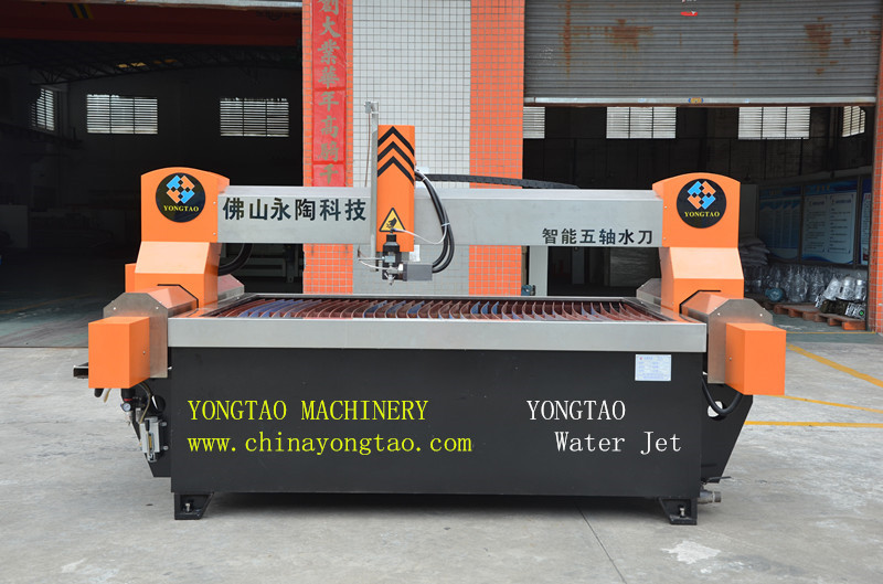
Factories selecting equipment for different materials, table sizes and cutting-angle requirements can compare Yongtao’s 3-axis, AB 5-axis and AC 5-axis waterjet configurations. The correct system should be confirmed according to the finished-part drawing, material, thickness, edge requirement and planned production volume.
Check the material, thickness, workpiece support, cutting-head condition, water supply, abrasive delivery, high-pressure connections, CNC program, cutting origin, piercing positions and available motion clearance. A dry run and first-part inspection are recommended for unfamiliar or high-value jobs.
Begin with a stable, previously verified setup. Inspect the first part at both the top and lower edges, identify the main defect and adjust only the parameter connected to that defect. Cutting speed, abrasive flow, nozzle condition, height stability, piercing strategy and workpiece support should be evaluated as an interacting system.
The jet loses energy and may lag as it passes through the material. Excessive cutting speed, insufficient effective cutting energy, unstable abrasive flow, nozzle wear or excessive nozzle distance can make lower-edge striations more visible. Inspect process stability before simply reducing speed.
Place the pierce point in scrap material, use a suitable lead-in and select a controlled piercing method. Material support, nozzle height, cutting-head condition and entry settings should also be checked. Always test unfamiliar brittle materials before processing the finished workpiece.
No. The suitable pressure depends on the pump, cutting-head components, material, thickness, speed and required edge quality. Stable pressure at an appropriate setting is more useful than an unstable peak value. Operators should follow the equipment and component manufacturer’s permitted operating range. For a detailed explanation of pressure selection, see the Waterjet Cutting Pressure Guide.
No. Abrasive flow must match the water stream, orifice, focusing tube, pressure and material. Too little abrasive can reduce cutting performance, while too much can interfere with mixing, increase consumption and accelerate wear. Stable delivery is as important as the selected quantity.
Stacking can improve output when identical parts are required, but the layers must be aligned and securely supported. Gaps between sheets can disturb the jet and reduce lower-layer quality. The complete stack should be test-cut and inspected before batch production.
Record parameters whenever a new material, thickness, part design, nozzle combination or quality requirement is introduced. Also update the record when a process change produces a verified improvement. The final approved settings should be available to every operator handling the same job.
Compare the current result with the approved first part and previous process record. Check material variation, pressure stability, abrasive delivery, nozzle wear, cutting-head alignment, nozzle height and workpiece movement. Change one factor at a time so the actual cause can be identified.
This guide was prepared and reviewed by the Yongtao Machinery technical team based on abrasive waterjet setup, cutting-test and production-support experience. Actual settings should be confirmed according to the machine configuration, material, thickness, component specifications and required finished quality.
0086-18665475362
[email protected]
Road 3, Wuzhuang Xiaofengtian Ind. Zone, Luocun Town, Nanhai Dist., Foshan, Guangdong, China